
MANUAL ROOF FANS008


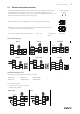

Table Of Contents
- 1 General information
- 2 Important safety information
- 3 Warranty
- 4 Delivery, transport, storage
- 5 Description
- 6 Name plate and type key
- 7 Accessories
- 8 Installation
- 9 Electrical connection
- 10 Commissioning
- 11 Operation
- 12 Troubleshooting/maintenance/repair
- 13 Cleaning
- 14 Deinstallation/dismantling
- 15 Disposal
- 16 Commissioning Report

Electrical connection |
15
9.1 Electrical connection accessories
The following wiring diagrams show the electrical connections between accessories and
fans (with EC motor) or frequency converters (e.g. FRQ, FRQS, FXDM) which can be
controlled with a 0–10V signal. If you are not sure if your fan is equipped with an EC- motor
please see chapter 6 Name plate and type key, page 9.
motor/frequency
converter
All fans with EC motors are equipped with a pre-wired potentiometer (0–10V).
10V
GND
0-10V
♦ The potentiometer must be disconnected if the fan should be controlled by other
accessories via 0–10V (e.g. accessories below).
10V
GND
0-10V
Wire- colours of motors with carried out cables: +10V = red 0..10V/PWM =
yellow
GND = blue
Controll via 0–10V signal
MTP 10 MTP 20
S-5EC/FRQ
S-5EC/FRQ
10V
GND
A
EC-Basic
MTV—1/10
EC-Vent
EC-Vent
IN/10V
OUT/PWM
GND
IN/RPM TACH
+10V
0...10V/PWM
GND
optional
PWM
Controll via switching on / off
The following fans are equipped with a DIN1 connection:
DVC(I) 560... DVC(I) 710... DVN(I) 500EC...
— —
DVC(I) 630... DVN(I) 450EC-K... DVN(I) 560EC...
— —
Din1: enable electronics
• enable: pin open or voltage 5–50 V DC
• disable: bridge to GND
CO2RT-R(-D)
IR24–P
24V AC
CO2RT-R-D
Supply
Neutral
Common
Relay NO
Relay NC
+10V
0...10V
GND
Din1
24V AC or DC
IR24-P
24V
Neutral
Common
Relay NO
Relay NC
+10V
0...10V
GND
Din1
| 008