
IOM SYSVRF2 AHU BOX0620 20220209 134828067 20220209 140641571


14
Model
BOX 2290, 90200
BOX 200360, 360560
Max. Current of AC Motor and Drainage pump
3.5A
15A
Table 3-14
Table 3-15
Table 3-16
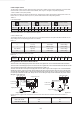
0-10V Output control
The DIP switch numbers of ENC2, ENC3 and ENC4 correspond to different voltage outputs. Depending on the DIP switch
numbers of SW1-2, there are two control modes available, which are gear 1 and gear 3 fan speeds, respectively.
1. SW1-2 dialled to "OFF" (factory default)
ENC2, ENC3 and ENC4 are respectively defined as low, middle and high voltage output signals. By default, ENC2 is set to 2V,
ENC3 is set to 7V, and ENC4 is set to A (A is 10V). See the table below for their corresponding relations:
0-10V output Voltage
Note: ENC2<ENC3<ENC4. If not satisfied, fault H9 is reported.
ENC2
(2V Factory Default)
ENC3
(7V Factory Default)
ENC4
(10V Factory Default)
Fan output voltage of Low speed Fan output voltage of Middle speed Fan output voltage of High speed
Voltage(V)
Dial code 0
1
1
1
2
2
3
3
4
4
5
5
6
6
7
7
8
8
9
9
A
10
B
10
C
10
D
10
E
10
F
10
Voltage(V)
Dial code 0
1
1
1
2
2
3
3
4
4
5
5
6
6
7
7
8
8
9
9
A
10
B
10
C
10
D
10
E
10
F
10
2. SW1-2 dialled to "ON"
This indicates that the fan has only one fan speed. In this case, ENC2 indicates the fan speed while ENC3 indicates a 0-10V
output voltage for the corresponding gear. ENC4 is not defined.
ENC2 DIP
0
1
2 (by default)
3-F
Fan Speed
Low only
Middle only
High only
High only
LOW/MIDDLE/HIGH
LOW output
MIDDLE output
HIGH output
HIGH output
0-10V output
ENC3 voltage
ENC3 voltage
ENC3 voltage
ENC3 voltage
Corresponding voltage for the ENC3 DIP switch:
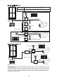
Wiring between the terminal block and fan
The sum current of the drainage pump and fan motor should not be greater than 3.5A in models AHU BOX 22/90 and 90/200.
The sum current of the drainage pump and fan motor should not be greater than 15A in models AHU BOX 200360 and 360560.
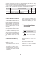
The unit should be equipped with molded case circuit breaker,refer to Table 3-17.
The AHU control box has a control port for single-phase AC motor; refer to Figure 3-18 and Figure 3-19. It has three different
speeds (high, medium, and low), the output voltage will also be the same as the input power of the box. Figure 3-18 and Figure
3-19 show the wiring diagram. Figure 3-18 is the recommended wiring in these two ways. In Figure 3-18, the AHU control box
is not directly connected to the fan motor. Always use it as a motor driving the relay contacts. Otherwise, the product could be
damaged or a fire could occur.
If wiring as shown in Figure 3-19, the maximum current of the fan motor must not exceed the value shown in Table 3-17.
Table 3-17
Figure
3-18
CN2 CN3 CN4
L
HIGH
N
N
MIDDLE
LOW
fan
motor
L N
MIDDLE
LOW
HIGH
N
single-phase power
single-phase AC motor
CN2 CN3 CN4
L
HIGH
N
N
MIDDLE
LOW
single-phase AC motor
fan
motor
Figure
3-19
single-phase power
molded case
circuit breaker
Molded case circuit breaker
6A
20A
molded case
circuit breaker
single-phase power