
SYSVRF2 CASSETTE IM


12
3) After the refrigerant pipe is connected to the indoor and outdoor
units, expel air as instructed in the “Expel air” section. After expelling
the air, screw the nut in the maintenance hole. a. Precautions for the
flexible part of the pipeline
i. The bend angle must not exceed 90°. (See Fig.6-2)
ii. The bend shall be preferably in the middle of the pipe length and
higher bend radiuses are preferred.
iii. Do not bend the flexible pipe more than 3 times.
b. Bend the thin-wall connective pipe (See Fig.6-3)
i. When bending the pipe, cut out a notch at the desired size at the
bend of the adiabatic pipe, and then expose the pipe (wrap the pipe
with the wrapping tape after bending it).
ii. The radius of the elbow pipe should be as large as possible to
prevent flattening or crushing.
iii. Use the pipe bender to close the elbow pipe.
c. Buy and use a copper pipe
When the copper pipe is purchased from the market, use the same
type of heat insulation materials (with a thickness of over 9 mm).
2. Deploy the pipelines
1) Drill a porthole on the wall, and put the hole sheath and hole
cover through the wall.
2) Place the connective pipe together with the indoor & outdoor
connection wires. Use wrapping tape to tie them tightly. Do not let
air enter or condensation will form.
3) Pull the connective wrapped connective pipe from outdoors
through the sheath, through the wall, and lead it into the room.
3. Make a vacuum from the connective pipeline.
4. After the above steps are completed, the spool of the valve of
the outdoor unit should be completely open, and the refrigerant
pipeline of the indoor unit and the outdoor unit should be smooth.
5. Use a leak detector or soapy water to detect leaks.
6. Put on an adiabatic envelope (accessory) on the connective
pipe adapter for the indoor unit and wrap it tightly with wrapping
tape to prevent condensation from forming and leaks.
Fig.6-2
Fig.6-3
Use your thumb to bend the pipe
Minimum radius 100 mm
Method for unravelling the spooled pipe.
Straighten the pipe end
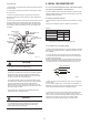
6.4 Pipeline connection
1. Flare
1) Use a pipe cutter to cut off the pipe (See Fig.6-4)
90
Burr
Slant
Coarse
Fig.6-4
2) Pull the pipe into the rear flare of the connective nut. (Refer to
Table: 6-3)
φ6.4
φ9.5
φ12.7
φ15.9
φ19.1
A(mm)
8.7
12.4
15.8
19.0
23.3
8.3
12.0
15.4
18.6
22.9
Table: 6-3
Max. Min.
2. Tighten the nut
Align with the connective pipe, start fastening the connection pipe
nut by hand and use a spanner to tighten it as shown in Fig.6-5.
Fig.6-5
CAUTION
According to the installation conditions, excessive torque will
damage the flaring and too little will lead to looseness and leaks.
Determine the tightening torque by referring to the table: 6-4.
Table: 6-4
Outer
diameter
(mm)
R0.4~0.8
45
°
±
2
90
°
±
4
A
TorqueTubing size
14.2~17.2 N.m (144~176 kgf.cm)
32.7~39.9 N.m (333~407 kgf.cm)
49.5~60.3 N.m (504~616 kgf.cm)
61.8~75.4 N.m (630~770 kgf.cm)
97.2~118.6 N.m (990~1210 kgf.cm)
Φ6.4mm
Φ9.5mm
Φ12.7mm
Φ15.9mm
Φ19.1mm