SYSVRF2 CASSETTE *% Cassette indoor unit INSTALLATION MANUAL
CONTENTS Strictly perform installation according to these installation instructions. If installation is defective, it may cause water leaks, electric shocks, or a fire. PAGE 1. PRECAUTIONS....................................................................................1 2. INSTALLATION INFORMATION...........................................................
If the refrigerant leaks during installation, ventilate the area immediately. Toxic gas may be produced if the refrigerant comes into contact with fire. 2. After completing the installation work, check that the refrigerant does not leak. Toxic gas may be produced if the refrigerant leaks into the room and comes into contact with a source of fire, such as a fan heater, stove or cooker. INSTALLATION INFORMATION To install the unit properly, please read this Installation Manual.
3. ATTACHED FITTINGS AND LOCAL PURCHASED COMPONENTS Please check whether all the following fittings have been included. If there are some spare fittings, please store them carefully. Table: 3-1 ATTACHED FITTINGS SHAPE NAME 1 1. Installation manual 8 2. Nut INSTALLATION FITTINGS QUANTITY 3. Washer 8 4. Installation paper board 1 5. Bolt M6 4 6. Soundproof / insulation sheath 2 7. Sponge I(250*250*8) 1 8. Sponge II(60*100*5) 1 9. Outlet pipe sheath 1 10. Outlet pipe clasp 1 11.
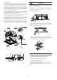
4.1 Installation place > 1000 mm (Refer to Fig. 4-1, Fig. 4-2, Fig. 4-3 and Table: 4-1 for specification.) > 1000 mm 4. INSTALLATION The indoor unit should be installed in a location that meets the following requirements: Avoid narrow spaces that are sensitive to noise. The ceiling must be flat and able to bear the weight of the indoor unit. > 1000 mm The outlet and the inlet must not be impeded and there must be minimal influence from the outside air. The air flow extends throughout the room.
3 Refer to 3 mentioned in the existing ceiling. WARNING 4 Remove the installation paper board. Install the unit in a location that can bear its weight. Insufficient support will cause the unit to fall, which may cause injury. Special installation methods can prevent the unit be blown around by strong winds or shocked by earthquakes. Improper installation can cause an accident. Unit body Central hole 4.
(Unit: mm) Φ32Drain pipe outer diameter Φ75New air supply orifice Fig. 4-7 ≥20 Install the hanger Ceiling 146 Hexagon nut (Adjust to balance) 46 Panel Main body Drain pipe Fig. 4-8 Fig. 4-9 Table: 4-2 10-12mm Main body of the unit Indoor unit model A(mm) B(mm) ≤ 8000 W 230 126 ≥ 9000 W 300 197 Ceiling Fig. 4-10 Fig. 4-11 NOTE All illustrations in this manual are for reference only. They may be slightly different from the air conditioner you purchased (depending on the model).
4.4 Procedure for installing the pendant bolt CAUTION Based on the unit structure, set the screw-pitch according to the size of the following figures: The bolt is high-quality carbon steel (galvanized or coated with other anti-rust materials) or stainless steel. The ceiling anti-rust measures must be conducted in line with actual construction. For details, consult a building engineer. Suspending bolts must be fixed.
3. Install the panel CAUTION 1) The part of the panel marked “PIPING SIDE” and “DRAIN SIDE” must be aligned with the piping outlet and drainpipe outlet from the main body. 1) Insert the sealant plastic cap in the sway motor in the notch of the water outflow pipe seal board. 2) Fix hooks of the panel at the swing motor and its opposite sides to the hooks of the corresponding water receiver. (Refer to Fig.4-15 a) Then hang the other two panel hooks onto the corresponding hangers of the body(Refer to Fig.
Slug Installation cover’s rope Slide the four sliders in the corresponding channel when installing the cover. Tap screw Fig.4-21 Fig.4-20 4.6 Install the distribution duct Conditioned air can be distributed by a distribution duct.
5. LAYOUT THE DRAIN PIPE CAUTION 5.1 Install the drain pipe of the indoor unit The joints in drain system must be sealed to avoid water leaks. 1) The drainpipe can use PVC pipe. (The external diameter about 37-39 mm. The inner diameter is 32 mm.) 9) The height from the floor to the end of the drainpipe or the bottom of drain slot must more than 50 mm. Don’t immerse the end of the drainpipe or the bottom of the drain slot into water.
5.2 Drain test 6. INSTALL THE CONNETING PIPE 1. Before testing, ensure that water can drained well and check all joints are sealed. 6.1 The connective length of indoor and outdoor piping and those height difference requirements. 2. The drainage test must be done before constructing the ceiling of a new house. Connect to different outdoor units with a different connective length based on height difference requirements. Please refer to Indoor Unit Installation Manual for details.
3) After the refrigerant pipe is connected to the indoor and outdoor units, expel air as instructed in the “Expel air” section. After expelling the air, screw the nut in the maintenance hole. a. Precautions for the flexible part of the pipeline i. The bend angle must not exceed 90°. (See Fig.6-2) 6.4 Pipeline connection 1. Flare 1) Use a pipe cutter to cut off the pipe (See Fig.6-4) Use your thumb to bend the pipe Slant 90 Coarse Burr Minimum radius 100 mm Fig.6-2 ii.
CAUTION Cut top-down Be cautious when installing the connective pipe. Do not let any air, dust or other foreign substance enter the system. Pipe connections should be conducted after the indoor and outdoor unit are fixed. Connective pipes must stay dry during installation. Connective copper pipes must be wrapped with an insulation layer (at least 9 mm thick). The temperature of the refrigerant circuit will be high. Keep the interconnection cable away from the copper tube Field piping side Unit body 7.
7.3 Indoor unit power 7-3-1 A special power supply is employed for indoor units that is different from the outdoor units’ supply. 7-3-2 Use a universal indoor power supply and electricity leakage protection devices and operating switches for indoor units that connect to the same outdoor unit. Outdoor power supply RCCB Wire slot Grounding line Indoor unit Grounding line Indoor power RCCB Signal wire for communicate indoor unit and outdoor unit Fig. 7-1 7.
(X1 X2) 8.2 Network address settings 1) The network address is set based on communication between the indoor and outdoor units. The address is the same as the indoor address, and there is no need to set them separately. 2) The central control of indoor units can be done on an outdoor unit. There is no need to control indoor unit separately. 3) For previous control of the indoor units, the network can be set by connecting (X, Y, E) terminals. There is no need to set the network address.
8.
9. TEST OPERATION 1 Testing must be carried out after installation is completed. 2 Please confirm the following points before the test: The indoor unit and outdoor unit are installed properly. The tubing and wiring have been correctly completed. The refrigerant pipe system has been checked for leaks. Drainage is unimpeded. The heating insulation works well. The ground wiring is connected correctly. The length of the tubing and the added stow capacity of the refrigerant have been recorded.
16126000002969 V5.