
User Manual


2-8
A1SAi & A1SRi Series Motherboard User’s Manual
Battery
JD1
FAN1
FAN2
FAN3
I-SATA4
I-SATA5
J1
J3
JPI2C1
JPW1
JSD1
JTPM1
VGA
LED8
LED3
LED7
JBT1
1
JOH1
JL1
JI2C1
JI2C2
JPK1
JWD1
JPG1
JIPMB1
COM2
COM1
JF1
USB 3.0-2
LAN3/4 LED
LAN2/LAN4
LAN1/LAN3
USB2.0-0/1
USB3.0-0/1
USB 3.0-3
IPMI_LAN
PCI-E 2.0 X8
DIMMA1
DIMMA2
DIMMB2
DIMMB1
I-SATA0
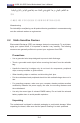
A1SAi/A1SRi Series Motherboard
Rev. 1.00
FP CTRL
JPL1
BIOS
Marvell
PHY
BMC
Bar Code
JUIDB1
CPU
SP1
I-SATA2
I-SATA3
I-SATA1
LED2
Caution: 1) To avoid damaging the motherboard and its components, please do
not use a force greater than 8 lb/inch on each mounting screw during motherboard
installation. 2) Some components are very close to the mounting holes. Please take
precautionary measures to avoid damaging these components when installing the
motherboard to the chassis.
2-4 Motherboard Installation
All motherboards have standard mounting holes to t different types of chassis.
Make sure that the locations of all the mounting holes for both motherboard and
chassis match. Although a chassis may have both plastic and metal mounting fas-
teners, metal ones are highly recommended because they ground the motherboard
to the chassis. Make sure that the metal standoffs click in or are screwed in tightly.
Then use a screwdriver to secure the motherboard onto the motherboard tray.
Tools Needed
Philips Screwdriver
(1)
Standoffs (4)
Only if Needed
Philips Screws (4)
Location of Mounting Holes