
Operating Instructions and Installation Instructions


26 | DHB-E SLi www.stiebel-eltron.com
INSTALLATION
Preparations
9. Preparations
9.1 Installation site
!
Material losses
Install the appliance in a room free from the risk of frost.
Always install the appliance vertically and near the draw-off
point.
The appliance is suitable for undersink and oversink installation.
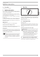
Undersink installation
1
2
26�02�02�0844
1 Cold water inlet
2 DHW outlet
Oversink installation
26�02�02�0845
2 1
1 Cold water inlet
2 DHW outlet
Note
Mount the appliance on the wall. The wall must have
a sufficient load-bearing capacity.
9.2 Water installation
- No safety valve is required.
Flush the water line thoroughly.
Taps/valves
Use suitable pressure taps/valves (see chapter "Installation/
Appliance description/ Accessories"). Open vented taps are not
permitted.
Note
Never use the 3-way ball shut-off valve in the cold water
inlet to reduce the flow rate. The 3-way ball shut-off valve
is intended to shut off the appliance.
Permissible water line materials
- Cold water inlet line:
Pipes made from galvanised steel, stainless steel, copper or
plastic
- DHW outlet line:
Pipes made from stainless steel, copper or plastic
!
Material losses
If plastic pipework is used, take into account the max-
imum inlet temperature and the maximum permissible
pressure (see chapter "Installation/ Specification/ Data
table").
Flow rate
Ensure that the flow rate for switching on the appliance is
achieved (see chapter "Installation/ Specification/ Data
table", On).
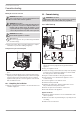
Increase the water line pressure if the required flow rate is
not achieved when the draw-off valve is fully open. If the
flow rate is not reached despite increasing the pressure, re-
move the flow limiter and install the plastic profile washer.
2
1
26�02�02�0820
1 Flow limiter
2 Plastic profile washer
Note
For the thermostatic valve to function correctly, the flow
limiter must not be replaced with the plastic profile wash-
er.