
Datasheet


Functionality LSM6DSL
32/114 DocID028475 Rev 7
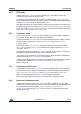
5.4 Block diagram of filters
Figure 5. Block diagram of filters
5.4.1 Block diagrams of the gyroscope filters
The gyroscope filtering configuration for both Mode 1 (for User Interface (UI) and Electronic
Image Stabilization (EIS) functionality) and Mode 2 is shown in Figure 6.
Figure 6. Gyroscope digital chain - Mode 1 (UI/EIS) and Mode 2
The gyroscope ODR is selectable from 12.5 Hz up to 6.66 kHz. A low-pass filter (LPF1) is
available, for more details about the filter characteristics see Table 68: Gyroscope LPF1
bandwidth selection.
Data can be acquired from the output registers and FIFO over the I
2
C/SPI interface.
$'&
+3)
+3B(1B*
/3)
/3)
/3)B6(/B*
63,,
&
),)2
)7<3( >@
2'5B*