
Brochure


Bulletin 30-10 / Page 21
Sporlan Solenoid Valves General
Purpose
The primary purpose of an electrically operated sole-
noid valve is to control automatically the flow of fluids,
liquid, or gas. Sporlan Solenoid Valves may be applied
on a wide variety of applications.
Basic Types
There are two basic types of solenoid valves. The
most common is the normally-closed type, in which
the valve opens when the coil is energized, and closes
when the coil is de-energized. The other type is the
normally-open valve which opens when the coil is de-
energized and closes when the coil is energized. The
operation of both types is discussed in the following
paragraphs.
Principles of Operation
Solenoid valve operation is based on the theory of
the electromagnet. The solenoid valve coil sets up
a magnetic field when electrical current is flowing
through it. If a magnetic metal, such as iron or steel, is
introduced into the magnetic field, the pull of the field
will raise the metal and center it in the hollow core of
the coil. By attaching a stem to the magnetic metal or
plunger, this principle is used to open the port of the
valve. When the electrical circuit to the coil is broken,
the magnetic field will collapse and the stem and
plunger either will fall by gravity or be pushed down
by the kick off spring.
Some solenoid valves are designed with a hammer
blow effect. When the coil is energized, the plunger
starts upward before the stem. The plunger then picks
up the stem by making contact with a collar at the top.
The momentum of the plunger assists in opening the
valve against the unbalanced pressure across the port.
Solenoid valves are also classified according to the
“stem and plunger” action. The two types are dis-
cussed in the following sections.
Direct Acting Solenoid Valves
With this type of valve, the stem and plunger assem-
bly opens the port of the valve directly. This type of
construction is limited to the smaller valves with port
sizes of less than 1/4 inch. Sporlan Solenoid Valves
of this design are the Types A3, E3, MA5A3, 180
Solenoid Pilot Control and W3P1.
Pilot Operated
Normally Closed Solenoid Valves
In a pilot operated valve, the stem and plunger as-
sembly opens a pilot port. This releases the pressure
on top of the disc, piston or diaphragm which then
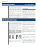
moves upward and opens the main valve port. Figure
3 illustrates the four phases of the operating cycle of a
typical pilot operated valve. The operation is the same
whether the valve is a disc, piston or diaphragm type.
Initially the pilot port and the main port are closed as
shown in A. Pressure at the valve inlet is present on
top of the disc as well, because of an equalizer hole
drilled through the disc.
When the coil is energized, the stem and plunger
assembly is lifted and the pilot port is opened — B.
The stem and plunger assembly is centered within the
coil by the magnetic field. The pilot port, if properly
sized for the fluid to be handled, will relieve the pres-
sure on top of the disc. Now the valve inlet pressure
will act on a portion of the bottom of the disc, lifting
the disc to open the main port — C. Once the port is
Figure 3
Coil Energized
Pilot Port Open
Main Port
About to Open
B
Coil Energized
Pilot Port Open
Main Port Open
C
Coil De-Energized
Pilot Port Closed
Main Port Closing
D
Coil De-Energized
Pilot Port Closed
Main Port Closed
A
Equalizer Hole