
User Guide


This technique may be carried further by using additional
evaporator sections, each controlled by a separate TEV and
refrigerant distributor. Using multiple evaporator sections
will let highly reduced loads to be properly controlled.
Single Evaporator Controlled by Two TEVs
For evaporator coils which are not split by design, i.e., row
split, face split, or interlaced, the following techniques may
be employed to improve part-load operation.
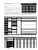
Figure 10 illustrates the use of two TEVs and two distribu-
tors feeding a single evaporator. Each evaporator circuit is
fed by two distributor circuits, one from each distributor.
The solenoid valves are connected to the compressor capac-
ity modulating system as mentioned before. Using this con-
figuration, TEV and distributor capacities can be reduced in
three stages. As an example, assume that TEV and distribu-
tor combination A are sized to handle 67% of the load and
combination B 33% of the load. The three stages of valve and
distributor capacity reduction result from opening or closing
the solenoid valves according to the following table:
Another variation of this technique is to have each evapo-
rator circuit fed by a single distributor circuit and size the
TEVs and distributors on the expected load of the total
number of circuits fed by each TEV. Reducing evaporator
capacity is accomplished by closing a solenoid valve which
deactivates the circuits being fed by the TEV and distributor
downstream of the solenoid valve. This method of capacity
control, however, requires a degree of care since the heat
load on the evaporator circuits will be affected in the manner
in which circuits are deactivated.
The Types (E)BF and EBS valves feature a single pushrod
which extends through the port of the valve. See Figure 8.
The port and pushrod cross sectional areas are identical so
that the opening force created by pressure drop across the
port is canceled by the pressure drop across the pushrod.
Furthermore, excellent pin and port alignment is provided
by this design. Refer to the section, Effect of Pressure Drop
Across the Valve Port, on Page 4 for additional information.
The Type (E)BF valve with the ‘AA’ port was developed by
Sporlan in 1988. Its original design used a two pushrod con-
struction similar to the conventional Type F valve, and the
balanced design was achieved by the use of a third floating
rod located above the valve port. As with the single rod bal-
anced port construction, the floating rod causes the pressure
drop across it to offset the opening force created by the pres-
sure drop across the port.
The ‘AA’ port Type (E)BF valve was later redesigned in 1993
to a single pushrod construction like the other Type (E)BF
valve sizes. All ‘AA’ port valves carrying a ‘3393’ date code or
later will have the single pushrod construction.
System Design For Part-Load Conditions
On systems where the compressor can unload to 50 percent
of its rated capacity, care must be exercised when selecting
expansion valves and refrigerant distributors. If the com-
pressor can unload below 33 percent of its rated capacity,
special design considerations may be necessary to assure
proper TEV operation. Figures 9, 10, and 11 are piping sche-
matics illustrating three possible methods of balancing the
capacity of the TEV and distributor with the compressor dur-
ing low load operation. Recognized piping references such as
the equipment manufacturer’s literature and the ASHRAE
Handbooks should be consulted for further information on
this subject. Sporlan cannot be responsible for dam-
ages arising from improper piping practices or the
improper use of its products.
Two or More Evaporator Sections Handling the
Same Load
Figure 9 illustrates two parallel evaporators each controlled
by a separate TEV and refrigerant distributor. Each evapo-
rator shares half of the total common load. The liquid line
solenoid valve ahead of each TEV is electrically connected
to the compressor capacity modulating system. When the
compressor capacity is reduced to 50%, one of the two sole-
noid valves closes stopping refrigerant flow to one TEV. The
TEV remaining in operation will then have a rated capacity
approximately equal to the compressor capacity operating
50% unloaded.
BULLETIN 10-9 / Page 11
rosserpmoC
yticapaC
lluFfotnecreP
yticapaC
fonoitisoP
dioneloS
evlaV A""
fonoitisoP
dioneloS
evlaV B""
dnaevlaVlatoT
gnitubirtsiD
gnidaoL
fotnecreP
yticapaCdetaR
%001
nepO
nepO
%001
%38 83%
%76
desolC
%001
%05 75%
%33
desolC Open
%001
%61 50%
TEV and Distributor
Solenoid
Valve
Solenoid
Valve
Capacity Reduction – 2 or more evaporator sections
handling same load.
TEV and Distributor
Figure 9
Solenoid
Valve
"A"
TEV and Distributor
"A"
TEV and Distributor
"B"
Solenoid
Valve
"B"
Capacity Reduction – Single evaporator controlled with
2 TEVs and 2 Solenoid Valves.
Figure 10
Table 4