
User Guide


P4 becomes more significant to TEV operation the greater
the port area to effective diaphragm area ratio, and the
greater the pressure drop varies across the valve port.
Balanced Port TEVs
Sporlan introduced the concept of the balanced port thermo-
static expansion valve in 1946 on large tonnage Types T and
W valves. This concept provided the means to either largely
reduce or eliminate the effect of pressure drop across the valve
port. This design utilized a double seating piston operated by
a single pushrod. The two port construction divided the refrig-
erant flow in opposite directions, thereby providing a semi-
balanced pressure differential across the piston.
Improved balanced port designs resulted in a fully balanced
Type O valve, and then the Types (E)BF, SBF, and EBS
valves for smaller capacity applications. For additional infor-
mation on the types and applications of balanced port TEVs,
refer to Page 9, Thermostatic Expansion Valve Applications.
Equalization Method
As previously discussed on Pages 3 and 4, the operation of
the thermostatic expansion valve is determined by the rela-
tionship between three fundamental pressures: bulb pres-
sure, equalizer pressure, and equivalent spring pressure.
These pressures are illustrated in Figure 1. The equalizer
pressure is the evaporator pressure the valve senses. The
means used to transmit this pressure from the refrigeration
system to the underside of the valve diaphragm is referred
to as the equalization method.
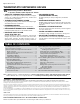
Evaporator pressure is transmitted to the underside of
the valve diaphragm by one of two methods. If the valve is
internally equalized, the evaporator pressure at the valve
outlet is transmitted to the diaphragm via a passageway
within the valve body or through a clearance around the
pushrods. If the valve is externally equalized, the under-
side of the valve diaphragm is isolated from the valve outlet
pressure by the use of packing material around the pushrods
or with pushrods which are closely fitted. Evaporator pres-
sure is transmitted to the diaphragm by a tube connecting
the suction line near the evaporator outlet to an external
fitting on the valve. The external fitting is connected to a
passageway which leads to the underside of the valve dia-
phragm. See Figure 2.
Internally equalized TEVs should be limited to single circuit
evaporator coils having a pressure drop no greater than the
equivalent of a 2°F saturated temperature change. Refer to
Table 1 for recommended maximum allowable pressure drop
values for internally equalized valves.
Externally equalized TEVs, however, are not affected by pres-
sure drop across the evaporator, including pressure drop from
refrigerant distributors employed by multi-circuited evaporator
IMPORTANT: The External Equalizer must be used on evaporators which
employ a refrigerant distributor.
coils. An externally equalized TEV may be used for all
refrigeration applications. It provides no operational dis-
advantages with respect to an internally equalized valve
other than requiring an external equalizer line be connected.
Figures 3, 4, and 5 illustrate the effects of evaporator pres-
sure drop on an internally and externally equalized TEV.
When an externally equalized TEV is used, the equalizer
connection on the TEV must be connected to the suction line
near the outlet of the evaporator, and not capped!
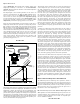
Figure 3 shows an internally equalized valve feeding a
single circuit evaporator which has no pressure drop. The
system refrigerant is R-22 and, for the purpose of illustra-
tion, R-22 is also used as the thermostatic charge. The
evaporator pressure at the valve outlet and at the sensing
bulb location is 52 psig. The sum of this pressure and the
12 psi spring pressure produces a 64 psig pressure in the
closing direction. For the valve to properly operate, a 64
psig opening bulb pressure is required to balance pressure.
Since the sensing bulb consists of liquid R-22, its pressure-
temperature characteristic is identical to the saturation
curve of R-22, and a 37°F bulb temperature is required. The
superheat at which the valve is controlling is calculated by
subtracting the saturation temperature of the evaporator
pressure at the sensing bulb location by the bulb tempera-
ture. In this case, the superheat is 9°F.
BULLETIN 10-9 / Page 5
Valve with INTERNAL
Equalizer
Close
Tolerance
Fit
Internal
Equalizer
External
Equalizer
Fitting
Push
Rods
Valve
Outlet
Pressure
Evaporator
Outlet
Pressure
Push
Rods
Valve with EXTERNAL
Equalizer
Figure 2
tnaregirfeR
erutarepmeTgnitaropaEv °F
04 02 0 – 02 – 04
porDerusserP is— p
431,21 a 00.2 05.1 00.1 57.0
––
––
22 00.3 00.2 05.1 00.1 75.0
705,205,A404 00.3 05.2 57.1 52.1 00.1
A(717 ainomm ) 00.3 00.2 05.1 00.1
Table 1
37°
52
52
52
64
Bulb Pressure
64 psig
Evaporator
Inlet Pressure
52 psig
Evaporator
Outlet Pressure
52 psig
Diaphragm
Spring Pressure
12 psi
Closing Pressure............................................................................= 52 + 12 = 64 psig
(Evaporator Inlet Pressure Plus Spring Pressure)
Bulb Pressure Necessary to Open Valve..........................................................64 psig
Bulb Pressure Equivalent to 64 psig.....................................................................37°F
Saturated Temperature Equivalent to Evaporator Outlet Pressure.........................28°F
SUPERHEAT......................................................................................................9°F
Bulb Temperature Minus Saturated Evaporator Temperature
12
Converted to Temperature = 37°F
Figure 3