
User Guide


R-408A, R-409A, R-502 and R-507. R-717 (ammonia) capaci-
ties listed in Catalog R/S 717 are based on 86°F. For other
liquid temperatures, apply the correction factor given in the
tables for each refrigerant.
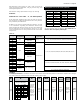
3. Select valve from the capacity tables — Select a valve
based on the design evaporating temperature and the available
pressure drop across the valve. If possible, the valve capacity
should equal or slightly exceed the design rating of the system.
Be sure to apply the appropriate liquid temperature and pres-
sure drop correction factors to the valve ratings shown in the
tables. Once the desired valve capacity has been located, deter-
mine the nominal capacity of the valve from the second column
of the tables. On multiple evaporator systems, select each valve
on the basis of individual evaporator capacity.
4. Determine if an external equalizer is required — The
amount of pressure drop between the valve outlet and bulb
location will determine if an external equalizer is required.
Refer to the section, Equalization Method, on Page 5 for fur-
ther information on this subject.
5. Select body type — Select the body type from Table 10
according to the style connections desired. For complete
specifications on each TEV type including nominal ratings,
refer to Bulletin 10-10 for valve’s specifications.
6. Select the Sporlan Selective Thermostatic Charge — Select
the charge according to the design evaporating temperature from
the Table on Page 18. Refer to Pages 7 thru 9 for a complete dis-
cussion of the Sporlan Selective Thermostatic Charges available.
Selection Example
Refrigerant 22
Application: air conditioning
Design evaporator temperature ....................40°F
Design condenser temperature ..................105°F
Refrigerant liquid temperature .....................90°F
Design system capacity ..............................2 tons
Available pressure drop across TEV:
Condensing pressure (psig) .................. 211
Evaporating pressure (psig) .................... 69
____
142
Liquid line and accessories loss (psi) ...... 7
Distributor and tubes loss (psi) 1 ......... 35
____
100
Refrigerant liquid correction factor .............. 1.06
Pressure losses in the liquid line result from friction and static
pressure losses. Minimizing these pressure losses as much as
possible is necessary for proper system design. Friction losses
may be minimized by properly sizing the liquid line and liq-
uid line accessories such as a solenoid valve and filter-drier.
Static pressure losses, however, are solely the result of the
weight of the vertical height of refrigerant liquid. As a result,
static pressure losses can only be minimized by reducing the
upward vertical height refrigerant liquid must travel. Table 8
may be used to determine the static pressure loss of a liquid
line. When the sum of the static pressure and friction losses
are known, the amount of subcooling necessary to prevent
vapor from forming in the liquid line can be determined. For
example, if the sum of the static and friction losses is 14 psi
for an R-22 system, and the condensing temperature is 100°F,
the subcooling necessary is as follows:
saturation pressure of R-22 at 100°F condensing = 196
psig pressure at TEV inlet = 196 -14 = 182 psig
saturation temperature of R-22 liquid at 182 psig = 95°F
subcooling required = 100 - 95 = 5°F
Refrigerant Liquid Temperature and Pressure Drop
Across TEV
The refrigerant liquid temperature entering the TEV and the
pressure drop available across the TEV influence valve capac-
ity. The valve capacity ratings displayed in Bulletin 10-10,
are based on 100°F vapor free liquid entering the valve for
R-12, R-22, R-134a, R-401A, R-402A, R-404A, R-407A, R-407C,
R-408A, R-409A, R-502, and R-507. R-717 (ammonia) valve
capacity ratings listed in Catalog R/S 717 are based on 86°F
vapor free liquid entering the valve. Liquid correction factors for
other liquid temperatures are included in Bulletin 10-10 along
with the ratings tables for each of the refrigerants listed above.
The tables also provide valve capacities for typical pressure
drops across the TEV.
Thermostatic Charge
The pressure-temperature curves of the various Sporlan Selective
Charges have different characteristics. The same amount of
superheat will not produce equal valve openings for each type of
charge. The valve capacity ratings shown in this bulletin specify
the thermostatic charges which they are based on.
SELECTION PROCEDURE
The following procedure should be used when selecting a
Sporlan TEV:
1. Determine pressure drop across valve — Subtract the
evaporating pressure from the condensing pressure. The
condensing pressure used in this calculation should be the
minimum operating condensing pressure of the system.
From this value, subtract all other pressure losses to obtain
the net pressure drop across the valve. Be sure to consider
all of the following possible sources of pressure drop: (1)
friction losses through refrigeration lines including the
evaporator and condenser; (2) pressure drop across liquid
line accessories such as a solenoid valve and filter drier; (3)
static pressure loss (gain) due to the vertical lift (drop) of
the liquid line; and (4) pressure drop across a refrigerant
distributor if used. Table 9 specifies typical pressure drops
across Sporlan type refrigerant distributors at design load
conditions. Refer to Bulletin 20-10 for further information
on refrigerant distributors.
2. Determine the liquid temperature of the refrigerant
entering the valve — The TEV capacity tables in Bulletin
10-10, are based on a liquid temperature of 100°F for R-12,
R-22, R-134a, R-401A, R-402A, R-404A, R-407A, R-407C,
Page 16 / BULLETIN 10-9
RECOMMENDED
VCP100, VGA
VZ, VZ
EVAPORATOR
20° 0° -10°
0.22 0.19 0.17
0.27 0.25 0.22
0.38 0.33 0.27
0.49 0.43 0.35
CAPACITY (tons)
EVAPORATING TEMP
Condensing
Temp. (F)
80 0.41 0.56 0.69
90 0.37 0.53 0.66
100 0.33 0.49 0.62
0 5 10
The valve capacity
should equal or slightly exceed
the tonnage rating of the system
Design
evaporating
temperature