
Operation Manual


1.
2.
3.
4.
5.
6.
7.
8.
9.
10.
11.
12.
13.
14.
15.
16.
17,
18
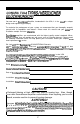
Kev to
Callouts
+12V
-
Connected to fuse or circuit breaker, then battery’s positive post.
Ground Main ground connection. Bolt to a clean chassis ground in the
vehicle.
Remote Remote turn-on input from the head unit. Accepts
+12V.
Speaker Output Connections Channels 1
&
2.
Speaker Output Connections Sub Channels.
Speaker Output Connections Channels 3
&
4.
Inputs Right and left channel inputs for channels 1
8
2.
Crossover Adjustment Pot
-
Crossover frequency setting for the channels
1
8
2 high pass
filter.Subwoofer
Crossover Switch Select “IN”
to
use
the
amplifier’s internal low pass filter, or
uOUT”
to use an external crossover.
Crossover Adjustment Pot Crossover frequency setting for the
subwoofer low pass filter.
LED Indicates amplifier power on.
Crossover Adjustment Pot
-
Crossover frequency setting for the channels
3 8 4 high pass filter.
inputs
Right and left channel inputs for channels 1
& 2 and the subwoofer.
Channels 3 & 4
input
Select
-
Switches to allow all channels to be driven
from 2 (CH 1 & 2) or 4 RCA inputs
inputs Right and left channel inputs for channels 3 8 4.
Channels 1
8
2 Crossover Switch
-
Select “IN” to use the amplifier’s
internal high pass filter.
or
‘“OUT” to bypass the internal crossover.
Input Level -Variable from
100mV
to
2.5V-Channels
1
&
2.
Input Level
-
Variable from 40mV to
2.5V-Subwoofer
Channel.
Input Level -Variable from
IOOmV
to
XV-Channels
3
&
4.
Channels 3 & 4 Crossover Switch
-
Select “IN” to use the amplifier’s
internal high pass filter, or “OUT” bypass the internal crossover.