
Operation Manual


1.
2.
3.
4.
5.
6.
7.
8.
9.
10
11
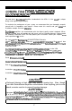
+12V
Connected to fuse or circuit breaker, then battery’s positive post.
Ground Main ground connection. Bolt to a clean chassis ground in the
vehicle.
Remote
-
Remote turn-on input from the head unit. Accepts
+12V.
Speaker Output Connections-Channels 1 8 2.
Speaker Output Connections Sub Channels.
Crossover Adjustment Pot
-
Crossover frequency setting for the
subwoofer low pass filter.
Input Level Variable from 40mV to
2.5V-Subwoofer
Channel.
Crossover Switch Select “IN” to use the amplifier’s internal high pass
filter, or “OUT” to bypass the internal crossover.
Crossover Adjustment Pot-Crossover frequency setting for the channels
1
&
2 high pass filter.
12. LED Indicates amplifier power on.
Input Level -Variable from
IOOmV
to
2.5V-Channels
1
&
2.
Inputs
-
Right and left channel inputs for channels
1
& 2 and the subwoofer.
Key to Cal/outs
5