
Operation Manual


Soundcraft Vi Series™ User Guide 1112 Page 2 - 13
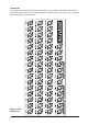
STAGE BOX
The Stage Box contains 12 Slots for 6U-high Audio I/O Cards, a GPIO/LED Card and the MADI HD Card
which contains the Stage Box-to-Local Rack connection.
Slots are labelled from left to right A-L, and the connectors on the cards are numbered from top to bottom
1-8. These labelling references are used by the patching system (see chapter 11) when the user wishes to
patch the connectors to input channels or output busses.
The primary power supplies and the ventilation monitoring connector can be found on the rear panel.
Stage Box Description
Primary power supply
The primary power supply connects directly to the IEC inlet and provides a full range ac inlet, converting
100V to 240V ac to 24V dc. The Stage box can hold up to two power supplies, providing redundancy for
those that require it.
Audio I/O Cards
The following cards are supported.
6 X Mic/Line Input cards each providing eight electronically balanced Mic/Line Input channels,
each with digitally-controlled analogue gain, a 20dB pad, a 80Hz low-cut lter, and phantom
power.
3 X Line Output cards, each providing eight line output channels.
Optional Cards
AES Input card, providing 8 AES input channels (replaces 1 Mic/Line Input card).
AES Output card, providing 8 AES output channels (replaces 1 Mic/Line Output card).
Card Function Overview
Input card
Input cards handle 8 x mic amp, phantom power, pad, analogue low pass lter, phase reverse and A to
D. The card has an internal ID, which indicates whether it is input or output and analogue or digital. This
means that the system can automatically recognise if the card conguration has been changed.
Output Card
Output cards handle 8 x D to A. The card has a set of relays, which will mute the outputs if the power fails.
The module type is identied by the internal ID of the module.
Normally 3 output cards are tted, giving 24 outputs, however, more cards, up to a maximum of 8 cards
giving 64 outputs, can be tted if input cards are removed.
LED/GPIO/Status card.
Handles GPIO, which is controlled remotely from the Control Surface. The inputs are on opto-isolators and
the outputs are open collector transistor outputs. The card also has status indicators for power rails, clock
status and IO, and a RECONFIG button which must be pressed if the card conguration has been changed.