
Installation Guide
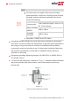


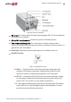

Figure 9: Inverter Interfaces
ACoutput: ACoutput gland, AC cable external gauge, M32 (15-21mm diameter)
for connection to the grid
AC and DC conduit entries: Connection points of the Safety Switch.
Two communication glands: for connection of inverter communication
options. Each gland has three openings. Refer to
Setting Up Communication
on
page 66 for more information.
Drain valve: Drains any moisture that may be accumulated in the unit.
ON/OFF/P Switch:
Figure 10: ON/OFF/P switch
ON (1) - Turning this switch ON (after optimizer pairing) starts the
operation of the power optimizers, enables power production and
allows the inverter to begin exporting power to the utility grid.
OFF (0) - Turning this switch OFF reduces the power optimizer voltage
to a low safety voltage and inhibits exportation of power. When this
switch is OFF, the control circuitry remains powered up.
P - Moving and releasing the switch allows viewing system information
via the LEDs and on the SolarEdge SetApp mobile application screen,
and performing the following functions:
Chapter 3: Installing the Inverter 29
Three
Phase
System
Installation
Guide
MAN-01-00527-1.2