
Installation Guide


Table Of Contents
- Disclaimers
- Support and Contact Information
- Revision History
- Contents
- HANDLING AND SAFETY INSTRUCTIONS
- IMPORTANT SAFETY INSTRUCTIONS
- Chapter 1: Introducing the SolarEdge Power Harvesting System
- Chapter 2: Installing the Power Optimizers
- Chapter 3: Installing the Inverter
- Chapter 4: Connecting the AC and the Strings to the Safety Switch
- Chapter 5: Commissioning the Installation
- Chapter 6: User Interface
- Chapter 7: Setting Up Communication
- Appendix A: Errors and Troubleshooting
- Appendix B: Mechanical Specifications
- Appendix C: External Fan Maintenance and Replacement
- Appendix D: Replacing and Adding System Components
- Appendix E: Determining the Circuit Breaker Size
- Technical Specifications - Single Phase Inverters (North America)
- Technical Specifications - Three Phase Inverters (North America)
Creating an Ethernet (LAN) Connection
This communication option enables using an Ethernet connection to connect the
inverter to the monitoring platform through a LAN.
Ethernet cable specifications:
Cable type – a shielded Ethernet cable (Cat5/5E STP) may be used
Maximum distance between the inverter and the router – 100 m/ 330 ft.
NOTE
If using a cable longer than 10 m / 33 ft in areas where there is
a risk of induced voltage surges by lightning, it is recommend
to use external surge protection devices.
For details refer to:
https://www.solaredge.com/sites/default/files/overvoltage_surge_
protection_na.pdf.
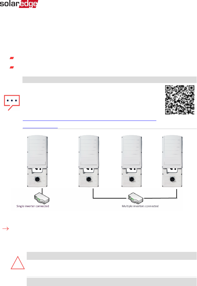
Figure 30: Example of Ethernet connection
To connect the Ethernet cable:
1. Remove the inverter cover as described in
Removing the Inverter Cover
on page 86.
2.
Open the communication gland #1.
CAUTION!
The gland includes a rubber waterproof fitting, which should be used to
ensure proper sealing.
ATTENTION!
Chapter 7: Setting Up Communication 87
Three Phase System Installation Guide MAN-01-00002-4.3