Operator’s Manual S200XT Series Description S200XTBV2861, 61” Cut Zero-Turn Riding Mower S200XTKAV2661, 61” Cut Zero-Turn Riding Mower S200XTBV3261, 61” Cut Zero-Turn Riding Mower S200XTB2861, 61” Cut Zero-Turn Riding Mower S200XTB3061, 61” Cut Zero-Turn Riding Mower S200XTBV3661, 61” Cut Zero-Turn Riding Mower S200XTKAV2661, 61” Cut Zero-Turn Riding Mower S200XTBV32, Zero-Turn Riding Mower S200XTB30, Zero-Turn Riding Mower S200XTBV36, Zero-Turn Riding Mower S200XT/72”, 72” Cut Mower Deck R Model 5900
Thank you for purchasing this quality-built SNAPPER PRO product. We’re pleased that you’ve placed your confidence in the SNAPPER PRO brand. When operated and maintained according to the instructions in this manual, your SNAPPER PRO product will provide many years of dependable service. This manual contains safety information to make you aware of the hazards and risks associated with this machine and how to avoid them.
Table of Contents Regular Maintenance ................................................25 Maintenance Schedule .........................................25 Checking/Adding Fuel ...........................................26 Fuel Filter ..............................................................26 Oil & Filter Change ...............................................26 Lubrication ............................................................27 Check Hydraulic Oil Level.....................................
Operator Safety Operating Safety Congratulations on purchasing a superior-quality piece of lawn and garden equipment. Our products are designed and manufactured to meet or exceed all industry standards for safety. Do not operate this machine unless you have been trained. Reading and understanding this operator’s manual is a way to train yourself. Power equipment is only as safe as the operator.
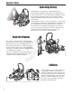
Operator Safety Slope Operation Operation on slopes can be dangerous. Using the unit on a slope that is too steep where you do not have adequate wheel traction (and control) can cause sliding, loss of steering, control, and possible rollover. You should not operate on a slope greater than a 5.4 foot rise over a 20 foot length (15 degrees). Always mow across slopes, not up and down (to maintain traction on the wheels) and avoid sudden turns or rapid speed changes.
Operator Safety Roll Bar Use Keep the roll bar in the raised position and fasten the seat belt. There is no roll over protection when the roll bar is down! Do not jump off if the mower tips (it is safer to be secured by the seat belt with the roll bar raised.) N ep o ro t fo du r ct io n Lower the roll bar only when necessary (such as to temporarily clear a low overhanging obstacle) and NEVER remove it. Do NOT use the seat belt when the roll bar is down. Raise the roll bar as soon as clearance permits.
Operator Safety Fuel and Maintenance Always disengage all drives, shutoff the engine, and remove the key before doing any cleaning, refueling, or servicing. Gasoline and its vapors are extremely flammable. Do not smoke while operating or refueling. Do not add fuel while engine is hot or running. Allow engine to cool for at least 3 minutes prior to adding fuel. Do not add fuel indoors, in an enclosed trailer, garage, or any other enclosed area that is not well ventilated.
Operator Safety Read these safety rules and follow them closely. Failure to obey these rules could result in loss of control of unit, severe personal injury or death to you, or bystanders, or damage to property or equipment. This mowing deck is capable of amputating hands and feet and throwing objects. The triangle in text signifies important cautions or warnings which must be followed. TRAINING PREPARATION R 1.
Operator Safety 23. Use care when approaching blind corners, shrubs, trees or other objects that may obscure vision. 24. To reduce fire hazard, keep unit free of grass, leaves & excess oil. Do not stop or park over dry leaves, grass or combustible materials.
Operator Safety EMISSIONS 1. Engine exhaust from this product contains chemicals known, in certain quantities, to cause cancer, birth defects, or other reproductive harm. 2. Look for the relevant Emissions Durability Period and Air Index information on the engine emissions label. IGNITION SYSTEM (GASOLINE MODELS) 1. This spark ignition system complies with Canadian ICES-002. SERVICE AND MAINTENANCE To avoid personal injury or property damage, use extreme care in handling gasoline.
Operator Safety leaks. Make sure all hydraulic fluid connections are tight and all hydraulic hoses and lines are in good condition before applying pressure to the system. If leaks occur, have the unit serviced immediately by your authorized dealer. 26. WARNING: Stored energy device. Improper release of springs can result in serious personal injury. Springs should be removed by an authorized technician. 27. Models equipped with an engine radiator: WARNING: Stored energy device.
Operator Safety WARNING Failure to properly inspect and maintain the seat belt can cause serious injury or death. INSPECT BUCKLE & LATCH INSPECTION AND MAINTENANCE OF THE ROLL BAR SEAT BELT • The seat belt like the ROLL BAR, needs to be periodically inspected to verify that the integrity has not been compromised through normal machine use, misuse, age degradation, modifications, or a roll over. If the seat belt does not pass all of the following tests, it should be replaced.
Operator Safety Safety Decals Before operating your unit, read the safety decals. The cautions and warnings are for your safety. To avoid a personal injury or damage to the unit, understand and follow all safety decals. A WARNING B If any safety decals become worn or damaged, and cannot be read, order replacement decals from your local dealer.
Operator Safety Safety Alert Symbol & Signal Words Safety Interlock System This unit is equipped with safety interlock switches. These safety systems are present for your safety, do not attempt to bypass safety switches, and never tamper with safety devices. Check their operation regularly. Operational SAFETY Checks Test 1 — Engine should NOT crank if: • PTO switch is engaged, OR • Parking brake is not engaged, OR • Motion control handles are not in the NEUTRAL position.
Features & Controls Safety Icons A Features and Controls B E C F G D Identification Numbers SA H M PL E I J N O L P When contacting your authorized dealer for replacement parts, service, or information you MUST have these numbers. Record your part number, serial number and engine serial numbers in the space provided on the inside front cover for easy access. These numbers can be found in the locations shown in Figure 1.
N ep o ro t fo du r ct io n Features and Controls Figure 2. Control Locations Control Functions The information below briefly describes the function of individual controls. Starting, stopping, driving, and mowing require the combined use of several controls applied in specific sequences. To learn what combination and sequence of controls to use for various tasks see the OPERATION section. Ground Speed Levers R These levers control the ground speed of the rider.
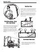
Features & Controls Fuel Tank Cap Parking Brake DISENGAGE Releases the parking brake. ENGAGE Locks the parking brake. To remove the cap, turn counterclockwise. Fuel Level Gauge Displays the fuel level in the tank. Pull the parking brake lever back to engage the parking brake. Move the lever fully forward to disengage the parking brake. NOTE: To start the unit the parking brake must be engaged. PTO (Power Take Off) Switch The PTO switch engages and disengages the mower.
Operation Operation General Operating Safety Before first time operation: Never operate on slopes greater than 15°. • Be sure to read all information in the Safety and Operation sections before attempting to operate this tractor and mower. • Become familiar with all of the controls and how to stop the unit. • Drive in an open area without mowing to become accustomed to the unit. WARNING Select slow ground speed before driving onto a slope.
Operation Check Tire Pressures Tire pressure should be checked periodically, and maintained at the levels shown in the chart. Note that these pressures may differ slightly from the “Max Inflation” stamped on the side-wall of the tires. The pressures shown provide proper traction, improve cut quality, and extend tire life. Tire Pressure Models: psi bar Rear 15 1,03 All Front 25 1,72 Models w/ Air Filled Tires Front N/A Models w/ Flat-Free Tires Figure 3.
Operation Foot Pedal Adjustment B A The deck lift foot pedal can be adjusted to accommodate the operator’s height for optimal comfort. C To adjust pedal position: 1. Remove the foot pedal (A, Figure 6) from the pedal mount tab (B). 2. Remove the pedal mount hardware (C) and rotate the tab 180 degrees. 3. Reinstall the pedal mount hardware and tighten securely. 4. Reinstall the foot pedal on the pedal mount tab in the proper orientation as shown in Figure 6. D Figure 6. Foot Pedal Adjustment A.
Operation Pushing the Rider By Hand Starting the Engine NOTICE WARNING If you do not understand how a specific control functions, or have not yet thoroughly read the FEATURES & CONTROLS section, do so now. Do NOT attempt to operate the tractor without first becoming familiar with the location and function of ALL controls. Towing the units will cause hydraulic transaxle and wheel motor damage. Do not use another vehicle to push or pull this unit. 1.
Operation Zero Turn Driving Practice Smooth Travel The lever controls of the Zero Turn rider are responsive, and learning to gain a smooth and efficient control of the rider’s forward, reverse, and turning movements will take some practice. The lever controls of the Zero Turn rider are responsive.
Operation Practice Turning Around a Corner Practice Turning In Place While traveling forward allow one handle to gradually return back toward neutral. Repeat several times. To turn in place, “Zero Turn,” gradually move one ground speed control lever forward from neutral and one lever back from neutral simultaneously. Repeat several times. NOTE: To prevent pivoting directly on the tire tread, it is best to keep both wheels going at least slightly forward.
Operation Mowing 1. Engage the parking brake. Make sure the PTO switch is disengaged, the motion control levers are locked in the NEUTRAL position and the operator is on the seat. 2. Start the engine (see Starting The Engine). 3. Set the mower cutting height (see Mowing Height Adjustment). 4. Set the throttle to FULL. 5. Engage the PTO by pulling up on the PTO switch. 6. Begin mowing. 7. When finished, shut off the PTO by pushing the PTO switch down completely.. 8.
Operation When and How Often to Mow The time of day and condition of the grass greatly affect the results you’ll get when mowing. For the best results, follow these guidelines: 1. Mow when the grass is between three and five inches high. 2. Mow with sharp blades. Short clippings of grass one inch or shorter decompose more quickly than longer blades. Sharp mower blades cut grass cleanly and efficiently, preventing frayed edges which harm the grass. 3. Mow at time of day when the grass is cool and dry.
Operation Proper Mulching Attaching A Trailer Mulching consists of a mower deck which cuts and recuts clippings into tiny particles and which then blows them down INTO the lawn. These tiny particles decompose rapidly into by-products your lawn can use. UNDER PROPER CONDITIONS, your mulching mower will virtually eliminate noticeable clippings on the lawn surface. The maximum weight of a towed trailer should be less than 200 lbs (91kg).
Regular Maintenance Regular Maintenance Maintenance Schedule The following schedule should be followed for normal care of your rider and mower. You will need to keep a record of your operating time. Determining operating time is easily accomplished by observing the elapsed time recorded by the hour meter.
Regular Maintenance Checking / Adding Fuel WARNING To add fuel: 1. Remove the fuel cap. 2. Fill the tank to about 1-1/2” (3,81 cm) of the bottom of the filler neck. This will allow for fuel expansion. NOTE: Do not overfill. Refer to your engine manual for specific fuel recommendations. 3. Install and hand tighten the fuel cap. Fuel Filter The fuel filter is located in the fuel line between fuel tank and carburetor, near the fuel pump.
Regular Maintenance Lubrication Lubricate the unit at the locations shown in Figures 20 through 23 as well as the following lubrication points. Grease: • front caster wheel axles & yokes • deck lift pivot blocks • mower deck spindles • mower deck idler arm Use grease fittings when present. Disassemble parts to apply grease to moving parts when grease fittings are not installed. Figure 20. Deck Lubrication Not all greases are compatible.
Regular Maintenance Check Hydraulic Oil Level Oil Type: 20W-50 conventional detergent motor oil. 1. Check the oil level when the unit is cold. The oil should be up to the “FULL COLD” mark on the transmission oil reservoirs (A, Figure 24). If the oil is below this level proceed to step 2. 2. Before removing the reservoir cap, make sure the area around the reservoir cap and fill neck of the reservoir is free of dust, dirt and other debris. Remove the reservoir caps. 3. Add oil up to the “FULL COLD” mark. 4.
Regular Maintenance Servicing The Mower Blades Removing the Mower Blade CAUTION Avoid injury! Mower blades are sharp. • Always wear gloves when handling mower blades or working near blades. 1. To remove the mower blade, use a 1” wrench on the flats of the spindle shaft and remove the mower blade mounting bolt with a 15/16” wrench (Figure 26). 2. If there are no flats on the spindle shaft, wedge a wooden block between the mower blade and the mower deck housing to keep the mower blade from turning.
Regular Maintenance Sharpening the Mower Blade A CAUTION Avoid injury! Mower blades are sharp. • Always wear gloves when handling the mower blades. • Always wear safety eye protection when grinding. Balancing the Mower Blades CAUTION Figure 29. Sharpening the Mower Blade A. Mower Blade Bevel B. Mower Blade Cutting Edge N ep o ro t fo du r ct io n 1. Sharpen the mower blades with grinder, hand file, or electric blade sharpener. 2.
Regular Maintenance Ground Speed Control Lever Adjustment The control levers can be adjusted in three ways. The alignment of the control levers, the placement of the levers (how close the ends are to one another) and the height of the levers can be adjusted. B A To Adjust the Handle Alignment Loosen the mount bolts (A, Figure 32) and pivot the lever(s) (B) to align with each other.
Regular Maintenance Neutral Adjustment B If the tractor “creeps” while the ground speed control levers are locked in NEUTRAL, then it may be necessary to adjust the linkage rod. NOTE: Perform this adjustment on a hard, level surface such as a concrete floor. 1. Disengage the PTO, engage the parking brake and turn off the engine. 2. There are two nuts (B, Figure 34) on the linkage rod. Loosen the nuts from the ball joints and turn the linkage rod (A) to adjust.
Regular Maintenance CAUTION Do not adjust the spring to be shorter than 2-11/16” (6,8 cm) when compressed. This may damage the brake mechanism. 7. Turn the adjustment nut (B) to compress of release the spring. 8. Engage the parking brake and re-measure the spring. Continue this process until the compressed spring length measures 2-3/4” (7 cm). 9. Position the set collar 1/8” (0,3 cm) away from the parking brake bracket and tighten. If this does not correct the braking problem, see your Snapper Pro dealer.
Regular Maintenance Deck Leveling Adjustment - 61” Models NOTE: Before adjusting the deck level, the deck lift rod timing must be checked and/or adjusted. Coarse Adjustment Procedure When adjusting the deck level, the coarse adjustment procedure should be used to make the majority of the adjustment and the fine adjustment procedure should be used to complete the adjustment. Adjust Here Figure 39. Hanger Chain Adjustment A N ep o ro t fo du r ct io n 1. Park machine on a flat, level surface.
Regular Maintenance Deck Rod Timing Adjustment - 72” Models Figure 42. Check Lift Rod Timing N ep o ro t fo du r ct io n 1. Park the machine on a flat, level surface. Disengage the PTO, engage the parking brake, turn off the engine, and remove the ignition key. Rear tires must be inflated to 15 psi (1,03 bar). 2. To check lift rod timing measure and record the distance between the lift pivots and the rod pivots. Repeat for other side of the unit. See Figure 42. 3.
Regular Maintenance Deck Leveling Adjustment - 72” Models B NOTE: Before adjusting the deck level, the deck lift rod timing must be checked and/or adjusted. A B A Figure 45. Hanger Chain Adjustment A. Jam Nut B. Deck Height Adjuster A N ep o ro t fo du r ct io n 1. Park the machine on a flat, level surface. Disengage the PTO, stop the engine and engage the parking brake. Check tires for proper inflation. 2. Lock the deck lift pedal in the 6” (15,2 cm) position.
Regular Maintenance Mower Belt Replacement A B NOTICE To avoid damaging belts, DO NOT PRY BELTS OVER PULLEYS. 1. Park the tractor on a smooth, level surface such as a concrete floor. Disengage the PTO, engage the parking brake, turn off the engine, and remove the ignition key. 2. Lower the mower deck to its lowest cutting position and remove the mower deck guards.
Regular Maintenance Check the Mower Belt Idler Tensioner Spring Length 1. Park the machine on a smooth level surface such as a concrete floor. Disengage the PTO, engage the parking brake, turn off the engine and remove the ignition key. 2. Lower the mower deck to its lowest cutting position. 3. Measure the coil length of the mower belt tensioner spring (A, Figure 49) and compare with the chart below. If the measurement does not match the chart, adjust the mower belt idler tensioner spring length.
Regular Maintenance Hydraulic Pump Drive Belt Replacement 1. Park the tractor on a smooth, level surface such as a concrete floor. Disengage the PTO, engage the parking brake, turn off the engine, and remove the ignition key. 2. Remove the PTO drive belt (see MOWER BELT REPLACEMENT for removal instructions). 3. Remove the hardware that secures the clutch anchor pad to the PTO clutch.
Regular Maintenance Battery Maintenance NOTE: This unit is equipped with a maintenance-free BCIU1 battery. Cleaning the Battery and Cables A WARNING Be careful when handling the battery. Avoid spilling electrolyte. Keep flames and sparks away from the battery. When removing or installing battery cables, disconnect the negative cable FIRST and reconnect it LAST. If not done in this order, the positive terminal can be shorted to the frame by a tool. Figure 52. Battery Compartment A.
Regular Maintenance Jump Starting With Auxiliary (Booster) Battery Battery Service Checking Battery Voltage WARNING Keep open flames and sparks away from the battery; the gasses coming from it are highly explosive. Ventilate the battery well during charging. A voltmeter can be used to determine condition of battery. When engine is off, the voltmeter shows battery voltage, which should be 12 volts. When engine is running, the voltmeter shows voltage of charging circuit which normally is 13 to 14 volts. 1.
Regular Maintenance Figure 53. Jump Starting WARNING N ep o ro t fo du r ct io n Discharged Vehicle Battery WARNING R Any procedure other than the preceding could result in: (1) personal injury caused by electrolyte squirting out the battery vents, (2) personal injury or property damage due to battery explosion, (3) damage to the charging system of the booster vehicle or of the immobilized vehicle.
Regular Maintenance Storage WARNING Temporary Storage (30 Days Or Less) Remember, the fuel tank will still contain some gasoline, so never store the unit indoors or in any other area where fuel vapor could travel to any ignition source. Fuel vapor is also toxic if inhaled, so never store the unit in any structure used for human or animal habitation.
Troubleshooting Troubleshooting Troubleshooting Chart While normal care and regular maintenance will extend the life of your equipment, prolonged or constant use may eventually require that service be performed to allow it to continue operating properly. The troubleshooting guide below lists the most common problems, their causes and remedies. See the information on the following pages for instructions on how to perform most of these minor adjustments and service repairs yourself.
Troubleshooting Rider Troubleshooting Continued. Problem Cause Remedy 1. 1. Turn valve(s) clockwise to close. 2. 3. 4. Hydraulic release valve(s) in “open” position. Belt is broken. Drive belt slips. Brake is not fully released. 1. 2. Pulleys or belt greasy or oily. Tension too loose. 3. Belt stretched or worn. 1. Clean as required. 2. Adjust spring tension. See Drive Belt Replacement 3. Replace belt. Brake will not hold. 1. 2. Brake is incorrectly adjusted. Brake pads worn. 1.
Troubleshooting Troubleshooting Common Cutting Problems PROBLEM CAUSE REMEDY Streaking 1. 2. 3. 4. 5. 6. 7. Blades are not sharp. Blades are worn down too far. Engine speed is too slow. Ground speed is too fast. Deck is plugged with grass. Not overlapping cutting rows enough. Not overlapping enough when turning. 1. 2. 3. 4. 5. Lawn is uneven or bumpy. Mower deck cutting height is set too low. Ground speed is too fast. Deck is not levelled correctly. Tire pressure is low or uneven. 1. 2. 3. 4. 5. 6.
Specifications Specifications NOTE: Specifications are correct at time of printing and are subject to change without notice. ENGINE 26 Gross HP† Kawasaki (Product Model: 5900937) Make Kawasaki Model FX730-AS00-R Displacement 44.3 Cu. in (726 cc) Electrical System 12 Volt, 15 amp. Alternator, Battery: 340 CCA Oil Capacity 2.2 US Qt. (2,1 L) w/ Filter 28 Gross HP* Briggs & Stratton (Product Model: 5900830) Make Briggs & Stratton Model 541777-0110-E1 Displacement 54.88 Cu.
48 www.SnapperPro.com 2 ALIGN THIS EDGE WITH A VERTICAL SURFACE (TREE, POLE, FENCE POST, BUILDING, ETC) EGREE 3 COMPARE THE ANGLE OF THE FOLD TO THE ANGLE OF THE SLOPE 1. Fold this page along the dotted line indicated above. 2. Align the left edge of this guide with a vertical tree, a power line pole, a fence post, or any vertical structure. 3. Compare the angle of the fold with the angle of the hill.
N ep o ro t fo du r ct io n R Notes
N ep o ro t fo du r ct io n R Notes
N ep o ro t fo du r ct io n R
BRIGGS & STRATTON PRODUCTS WARRANTY POLICY September 2012 LIMITED WARRANTY Briggs & Stratton warrants that, during the warranty period specified below, it will repair or replace, free of charge, any part that is defective in material or workmanship or both. Transportation charges on product submitted for repair or replacement under this warranty must be borne by purchaser. This warranty is effective for and is subject to the time periods and conditions stated below.
California, U.S. EPA, and Briggs & Stratton Corporation Emissions Control Warranty Statement Your Warranty Rights And Obligations The California Air Resources Board, U.S. EPA, and Briggs & Stratton (B&S) are pleased to explain the emissions control system warranty on your Model Year 2012--2013 engine/equipment. In California, new small off-road engines and large spark ignited engines less than or equal to 1.0 liter must be designed, built, and equipped to meet the State’s stringent anti-smog standards.
Operator’s Manual S200XT Series R N ep o ro t fo du r ct io n Ze ro -Tu r n R i d i n g M owe r s