Operator’s Manual S175X Series N ep o ro t fo du r ct io n Zero-Turn Riding Mowers 5900935 5900938 Description: R Model Number: S175XY20D52, 52” Cut Zero-Turn Riding Mower S175XY24D61, 61” Cut Zero-Turn Riding Mower BRIGGS & STRATTON POWER PRODUCTS GROUP, LLC.
Thank you for purchasing this quality-built SNAPPER PRO product. We’re pleased that you’ve placed your confidence in the SNAPPER PRO brand. When operated and maintained according to the instructions in this manual, your product will provide many years of dependable service. This manual contains safety information to make you aware of the hazards and risks associated with this machine and how to avoid them.
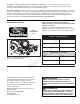
Table of Contents Operator Safety .................................................. 2 Safety Decals ........................................................11 Safety Icons ..........................................................12 Safety Interlock System ........................................12 Features & Controls ......................................... 13 Control Functions ..................................................13 Operation...........................................................
Operator Safety Operating Safety Congratulations on purchasing a superior-quality piece of lawn and garden equipment. Our products are designed and manufactured to meet or exceed all industry standards for safety. Do not operate this machine unless you have been trained. Reading and understanding this operator’s manual is a way to train yourself. Power equipment is only as safe as the operator.
Operator Safety Slope Operation Operation on slopes can be dangerous. Using the unit on a slope that is too steep where you do not have adequate wheel traction (and control) can cause sliding, loss of steering, control, and possible rollover. You should not operate on a slope greater than a 5.4 foot rise over a 20 foot length (15 degrees). Always mow across slopes, not up and down (to maintain traction on the wheels) and avoid sudden turns or rapid speed changes.
Operator Safety Roll Bar Use Keep the roll bar in the raised position and fasten the seat belt. There is no roll over protection when the roll bar is down! Do not jump off if the mower tips (it is safer to be secured by the seat belt with the roll bar raised.) N ep o ro t fo du r ct io n Lower the roll bar only when necessary (such as to temporarily clear a low overhanging obstacle) and NEVER remove it. Do NOT use the seat belt when the roll bar is down. Raise the roll bar as soon as clearance permits.
Operator Safety Fuel and Maintenance Always disengage all drives, shutoff the engine, and remove the key before doing any cleaning, refueling, or servicing. Gasoline and its vapors are extremely flammable. Do not smoke while operating or refueling. Do not add fuel while engine is hot or running. Allow engine to cool for at least 3 minutes prior to adding fuel. Do not add fuel indoors, in an enclosed trailer, garage, or any other enclosed area that is not well ventilated.
Operator Safety Read these safety rules and follow them closely. Failure to obey these rules could result in loss of control of unit, severe personal injury or death to you, or bystanders, or damage to property or equipment. This mowing deck is capable of amputating hands and feet and throwing objects. The triangle in text signifies important cautions or warnings which must be followed. TRAINING PREPARATION R 1.
Operator Safety 23. Use care when approaching blind corners, shrubs, trees or other objects that may obscure vision. 24. To reduce fire hazard, keep unit free of grass, leaves & excess oil. Do not stop or park over dry leaves, grass or combustible materials.
Operator Safety EMISSIONS 1. Engine exhaust from this product contains chemicals known, in certain quantities, to cause cancer, birth defects, or other reproductive harm. 2. Look for the relevant Emissions Durability Period and Air Index information on the engine emissions label. IGNITION SYSTEM (GASOLINE MODELS) 1. This spark ignition system complies with Canadian ICES-002. SERVICE AND MAINTENANCE To avoid personal injury or property damage, use extreme care in handling gasoline.
Operator Safety leaks. Make sure all hydraulic fluid connections are tight and all hydraulic hoses and lines are in good condition before applying pressure to the system. If leaks occur, have the unit serviced immediately by your authorized dealer. 26. WARNING: Stored energy device. Improper release of springs can result in serious personal injury. Springs should be removed by an authorized technician. 27. Models equipped with an engine radiator: WARNING: Stored energy device.
Operator Safety WARNING Failure to properly inspect and maintain the seat belt can cause serious injury or death. INSPECT BUCKLE & LATCH INSPECTION AND MAINTENANCE OF THE ROLL BAR SEAT BELT • The seat belt like the ROLL BAR, needs to be periodically inspected to verify that the integrity has not been compromised through normal machine use, misuse, age degradation, modifications, or a roll over. If the seat belt does not pass all of the following tests, it should be replaced.
Operator Safety Safety Decals Before operating your unit, read the safety decals. The cautions and warnings are for your safety. To avoid a personal injury or damage to the unit, understand and follow all the safety decals. 1 WARNING If any safety decals become worn or damaged, and cannot be read, order replacement decals from your local dealer.
Operator Safety Safety Icons The alert symbol is used to identity safety information about hazards that can result in personal injury. A signal word (DANGER, WARNING, or CAUTION) is used with the alert symbol to indicate the likelihood and the potential severity of the injury. In addition, a hazard icon may be used to represent the type of hazard. An explanation of hazard levels and icons are as follows: DANGER This indicates a hazard which, if not avoided, will result in serious injury or death.
Features and Controls Control Functions N ep o ro t fo du r ct io n Features and Controls The information below briefly describes the function of individual controls. Starting, stopping, driving, and mowing require the combined use of several controls applied in specific sequences. To learn what combination and sequence of controls to use for various tasks see the OPERATION section. R Ground Speed Levers These levers control the ground speed of the rider.
Features and Controls Deck Lift Pedal, Cutting Height Adjustment Pin & Deck Lift Lock Lever These control the cutting height of the mower deck. Depress the pedal until it locks into the 6” (15,2 cm) position. Place the adjustment pin in the desired cutting height and release the lift lock lever. Instrument Control Panel Voltage Gauge Gauge measures the output voltage of the engine charging system. Hour Meter The hour meter measures the number of hours the PTO has been engaged.
Operation Operation WARNING General Operating Safety Before first time operation: • Be sure to read all information in the Safety and Operation sections before attempting to operate this tractor and mower. • Become familiar with all of the controls and how to stop the unit. Do not use this machine on slopes greater than 15 degrees. Select slow ground speed before driving onto a slope. Use extra caution when operating on slopes with a rear-mounted grass catcher.
Operation Priming the Fuel System B Priming the fuel system removes any air bubbles from the fuel system. A WARNING Fuel leaked or spilled onto hot surfaces or electrical components can cause a fire. To help prevent possible injury, turn the ignition switch off when changing fuel filter or water separator element. Clean up fuel spills immediately. The fuel system would only need to be primed under the following conditions: • Before starting the engine for the first time.
Operation Pushing the Rider by Hand WARNING If you do not understand how a specific control functions, or have not yet thoroughly read the FEATURES & CONTROLS section, do so now. Do NOT attempt to operate the tractor without first becoming familiar with the location and function of ALL controls. Starting the Engine 1. While sitting in the operators seat, engage the parking brake, make sure the PTO switch is disengaged, and the ground speed control levers are locked in the neutral position. 2.
Operation Zero-Turn Driving Practice Smooth Travel The lever controls of the Zero Turn rider are responsive. Learning how to gain smooth, efficient control of the rider’s forward, reverse, and turning movements will take some practice. The lever controls of the Zero Turn rider are responsive.
Operation Practice Turning Around a Corner Practice Turning In Place While traveling forward allow one handle to gradually return back toward neutral. Repeat several times. To turn in place, “Zero Turn,” gradually move one ground speed control lever forward from neutral and the other lever back from neutral simultaneously. Repeat several times. NOTE: To prevent pivoting directly on the tire tread, it is best to keep both wheels going at least slightly forward.
Operation Mowing 1. Engage the parking brake. Make sure the PTO switch is disengaged, the motion control levers are locked in the NEUTRAL position, and the operator is on the seat. 2. Start the engine (see STARTING THE ENGINE). 3. Set the mower cutting height. 4. Set the throttle to FULL. 5. Engage the PTO by pulling up on the PTO switch. 6. Begin mowing. 7. When finished, shut off the PTO. 8. Stop the engine (see STOPPING THE RIDER AND ENGINE).
Operation When and How Often to Mow The time of day and condition of the grass greatly affect the results you’ll get when mowing. For the best results, follow these guidelines: 1. Mow when the grass is between three and five inches high. 2. Mow with sharp blades. Short clippings of grass one inch or shorter decompose more quickly than longer blades. Sharp mower blades cut grass cleanly and efficiently, preventing frayed edges which harm the grass. 3. Mow at time of day when the grass is cool and dry.
Operation Proper Mulching Attaching a Trailer Mulching consists of a mower deck which cuts and recuts clippings into tiny particles and then blows them down INTO the lawn. These tiny particles decompose rapidly into by-products your lawn can use. UNDER PROPER CONDITIONS, your mulching mower will virtually eliminate noticeable clippings on the lawn surface. The maximum weight of a towed trailer should be less than 200 lbs (91kg).
Operation Raise & Lower the Roll Bar To lower the roll bar: C 1. Pull the hair pin clips (A, Figure 11) out of the retainer pins (B). 2. Push or pull the top of the roll bar (C) forward against the rubber stops (D) and remove the retainer pins (B). 3. Lower the roll bar and reinstall the retainer pins and hair pin clips to secure the roll bar in the down position (see insert, Figure 11). D C To raise the roll bar: WARNING A B D Figure 11. Raise & Lower the Roll Bar A. Hair Pin Clip B.
Operation Storage WARNING Temporary Storage (30 Days Or Less) Remember, the fuel tank will still contain some fuel, so never store the unit indoors or in any other area where fuel vapor could travel to any ignition source. Fuel vapor is also toxic if inhaled, so never store the unit in any structure used for human or animal habitation.
Operation Check Tire Pressures Tire Pressure should be checked periodically, and maintained at the levels shown in the chart. Note that these pressures may differ slightly from the “Max Inflation” stamped on the side-wall of the tires. The pressures shown provide proper traction, improve cut quality, and extend tire life. Tire Pressure Front 25 psi (1,72 bar) Rear 18 psi (1,24 bar) Figure 12.
Operation Ground Speed Control Lever Adjustment The ground speed control levers can be adjusted in three ways. The alignment of the levers, the placement of the levers (how close the ends are to one another) and the height of the levers can be adjusted. B A To Adjust the Ground Speed Control Lever Alignment Loosen the mount bolts (A, Figure 14) and pivot the lever(s) (B) to align with each other.
Operation Mowing Height Adjustment The cutting height adjustment pin (A, Figure 16) controls the mower cutting height. The cutting height is adjustable between 1-3/4” (4,4 cm) and 5” (12,7 cm) in 1/4” (0,64 cm) increments. 1. Depress the deck lift foot pedal (B) until it locks into the 5” (12,7 cm) position. 2. Place the cutting height adjustment pin in the desired cutting height. 3. Depress the deck lift foot pedal then push the lock lever (C) towards the right to release the lock. 4.
Regular Maintenance Maintenance Maintenance Schedule & Procedures The following schedule should be followed for normal care of your rider and mower. You will need to keep a record of your operating time. Determining operating time is easily accomplished by observing the hour meter.
Regular Maintenance Checking / Adding Fuel To add fuel: 1. Remove the fuel cap (A, Figure 18). 2. Fill the tank to the bottom of the fill tube. This will leave room in the tank for fuel expansion. A NOTE: Do not overfill. Refer to your engine manual for specific fuel recommendations. 3. Install and hand tighten the fuel cap. 4. Repeat same process for opposite tank. WARNING Diesel fuel is highly flammable and must be handled with care.
Regular Maintenance Fuel Filter This unit is equipped with two fuel filters. One is a water seperator (A, Figure 19) and the other is a fuel filter (C). Both filters are located in the engine compartment on the right side of the engine. The water separator should be drained every 25 hours or whenever water is visible in the bowl. Replace both fuel filters every 500 hours of operation or as required. A To Replace the Fuel Filter: NOTE: Fuel filter is replaced as an assembly only.
Regular Maintenance Check / Add Engine Oil Level 3TNM68 Models Refer to Figure 20 for dipstick and oil fill locations. Refer to the engine owners manual for specific engine oil check and fill procedures. Also refer to the engine owners manual for specific engine oil and filter change procedures B Change Engine Oil & Filter A C D 3TNM72 Models B R N ep o ro t fo du r ct io n 1. Warm engine by running for a few minutes. (Refer to the engine operator’s manual for oil & filter replacement instructions.
Regular Maintenance Change Hydraulic Oil Filter Change Interval: Every 250 Hours Filter Part Number: 1719168 NOTE: Removing the oil filter from the filter base will drain the oil reservoir. Have a suitable container ready to catch any spilled oil. Ferris recommends this be a dealer-only service item. A Figure 22. Change Hydraulic Oil Filter A. Hydraulic Oil Filter N ep o ro t fo du r ct io n 1. Locate the transmission oil filter (A, Figure 22).
Regular Maintenance 3. If the coolant level is insufficient, remove the cap (E) from the reservoir and add coolant to the LOW (COLD) mark. See engine owners manual for specific engine coolant specifications. 4. Reinstall the cap. NOTE: Proper coolant mix is a 50/50 mixture of ethylene glycol and distilled water. See engine owners manual for engine coolant specifications. A Change Engine Coolant See engine owners manual for specific engine coolant procedures.
Regular Maintenance Figure 24. Deck Lubrication N ep o ro t fo du r ct io n Figure 28. PTO Drive Idler Arm Figure 25. Pump Drive Idler Arm Figure 29. Suspension Pivots Lubricating the Drive Shaft Maintenance Interval: Every 250 hours. R Figure 26. Control Handle Pivots & Seat Plate Pivots 1. Position the drive shaft so that the plug (A, Figure 30) can be accessed from beneath the machine through the hole in the engine cradle. 2. Remove the plug and install a 1/4-28 grease fitting. 3.
Regular Maintenance A A Figure 30. Drive Shaft (Bottom side of unit shown) A. Plug Figure 31. Front Caster & Wheel A. 1/4-28 Bolt Battery Maintenance F NOTE: This unit is equipped with a maintenance-free BCIU1 battery. Removing the Floor Pan to Access the Battery: E C N ep o ro t fo du r ct io n 1. (CE Models Only): Loosen and remove the floor pan retaining bolt (D, Figure 32). 2.
Regular Maintenance Servicing the Mower Blades Removing the Mower Blade CAUTION Avoid injury. Mower blades are sharp. • Always wear gloves when handling mower blades or working near blades. 1. To remove the mower blade, wedge a wooden block between the mower blade and the mower deck housing to keep the blade from turning and remove the mower blade mounting bolt with a 15/16” wrench (Figure 33). Figure 33.
Regular Maintenance Sharpening the Mower Blades A CAUTION Avoid injury. Mower blades are sharp. • Always wear gloves when handling mower blades or working near blades. • Always wear safety eye protection when grinding B 1. Sharpen the mower blade with a grinder, hand file, or electric blade sharpening. 2. Sharpen the mower blade by removing an equal amount of material from each end of the mower blade. 3. Keep the original bevel (A, Figure 36) when grinding. Do NOT change the mower blade bevel. 4.
Regular Maintenance Fuse Location The fuse block is located on the side of the instrument control panel mounted on the right hand side fuel tank. Refer to Figure 39 for the location and amperage of the fuses used in this machine. 5100983 S/N:2015276814 & Below A. B. C. D. A B E F PTO Clutch: 20 amp fuse Fuel Solenoid: 20 amp fuse Alternator: 20 amp fuse Main: 40 amp fuse C D S/N: 2015276815 & Above A. B. C. D.
Troubleshooting, Adjustment & Repair Troubleshooting While normal care and regular maintenance will extend the life of your equipment, prolonged or constant use may eventually require that service be performed to allow it to continue operating properly. The troubleshooting guide below lists the most common problems, their causes and remedies. See the information on the following pages for instructions on how to perform most of these minor adjustments and service repairs yourself.
Troubleshooting, Adjustment & Repair Rider Troubleshooting Continued. PROBLEM Engine runs, but rider will not drive. Rider drive belt slips. CAUSE REMEDY 1. Hydraulic release valve(s) in “open” position. 2. Belt is broken. 3. Drive belt slips. 4. Brake is not fully released. 1. Turn valve(s) clockwise to close. 1. Pulleys or belt greasy or oily. 2. Tension too loose. 2. See Drive Belt Replacement. 3. See problem and cause below. 4. See authorized service dealer 3. Belt stretched or worn. 1.
Troubleshooting, Adjustment & Repair Troubleshooting Common Cutting Problems PROBLEM CAUSE REMEDY 1. 2. 3. 4. 5. 6. Blades are not sharp. Blades are worn down to far. Engine speed is too slow. Ground speed is too fast. Deck is plugged with grass Not overlapping cutting rows enough. 7. Not overlapping enough when turning. 1. 2. 3. 4. 5. 6. 1. Lawn is uneven or bumpy. 2. Mower deck cutting height is set too low. 3. Ground speed is too fast. 4. Deck is not leveled correctly. 5.
Troubleshooting, Adjustment & Repair Neutral Adjustment If the tractor “creeps” while the ground speed control levers are locked in NEUTRAL, then it may be necessary to adjust the linkage rod. NOTE: Perform this adjustment on a hard, level surface such as a concrete floor. A B Figure 41. Neutral Adjustment (LH side shown) A. Adjustment Linkage Rod B. Nuts N ep o ro t fo du r ct io n 1. Disengage the PTO, engage the parking brake and turn off the engine. 2.
Troubleshooting, Adjustment & Repair Parking Brake Adjustment 1. Disengage the PTO, engage the parking brake, stop the engine and remove the ignition key. 2. This unit has two brake springs (A, Figure 43). The brake springs are located under the front of the fuel tanks. Locate the brake springs. See Figure 43. 4. With the parking brake engaged, measure the compressed spring length. The spring should be 1-1/8” (2,9 cm) when compressed.
Troubleshooting, Adjustment & Repair Deck Lift Rod Timing Adjustment Figure 44. Check the Deck Lift Rod Timing R N ep o ro t fo du r ct io n 1. Park the machine on a flat, level surface. Disengage the PTO, engage the parking brake, turn off the engine, and remove the ignition key. Rear tires must be inflated to 18 psi (1,24 bar); front tires to 25 psi (1,72 bar). 2. To check the lift rod timing, measure and record the distance between the lift pivots and the rod pivots. Repeat for other side of unit.
Troubleshooting, Adjustment & Repair Deck Leveling Adjustment NOTE: Before adjusting the deck level, the deck lift rod timing must be checked and/or adjusted. Coarse Adjustment Procedure When adjusting the deck level, the coarse adjustment procedure should be used to make the majority of the adjustment and the Fine Adustment Procedure should be used to complete the adjustment. CAUTION Figure 47. 2 X 4 Locations (Arrow points toward front of the deck) N ep o ro t fo du r ct io n 1.
Troubleshooting, Adjustment & Repair Fine Adjustment Procedure (52” Models Only) 1. Loosen the jam nut (A, Figure 50) and turn the fine adjustment bolt (B) to adjust the deck height until the back measurement equals 4” (10,2 cm). • Turn the bolt CLOCKWISE to raise the deck. B A • Turn the bolt COUNTER-CLOCKWISE to lower the deck. Figure 50. Fine Adjustment of the Deck Cutting Height A. Jam Nut B. Fine Adjustment Bolt R N ep o ro t fo du r ct io n 2.
Troubleshooting, Adjustment & Repair Hydraulic Pump Drive Belt Replacment To avoid damaging belts, DO NOT PRY BELTS OVER PULLEYS. B 1. Park the tractor on a smooth, level surface such as a concrete floor. Disengage the PTO, engage the parking brake, turn off the engine, and remove the ignition key. WARNING Use extreme caution when rotating the idler arm with the breaker bar, due to the increased tension in the spring as the idler arm is being rotated.
Troubleshooting, Adjustment & Repair 9. Install the drive belt on the idler arm pulley and check to make sure that the V-side of the belt runs in the pulley grooves. See Figure 52. 10. Carefully rotate the breaker bar CLOCKWISE and install the belt on the right pump drive pulley (B, Figure 52). Carefully release the tension on the breaker bar. 11. Reinstall the pump guard plate (B, Figure 51) and secure in place using the pump plate hardware (A). 12.
Troubleshooting, Adjustment & Repair PTO Clutch Belt Replacment Idler Arm Spring Adjustment G B E A N ep o ro t fo du r ct io n 1. Park the tractor on a smooth, level surface such as a concrete floor. Disengage the PTO, engage the parking brake, turn off the engine, and remove the ignition key. 2. Open the hood to gain access to the PTO clutch belts (A, Figure 55) which is located on the rear of the engine. 3. Remove the PTO clutch anchor bolt (B). 4. Disconnect the PTO clutch wire harness (G). 5.
Troubleshooting, Adjustment & Repair Mower Belt Replacement 52” Deck To avoid damaging belts, DO NOT PRY BELTS OVER PULLEYS. 1. Park the tractor on a smooth, level surface such as a concrete floor. Disengage the PTO, engage the parking brake, turn off the engine, and remove the ignition key. A WARNING B Use extreme caution when rotating the idler arm with the breaker bar, due to the increased tension in the spring as the idler arm is being rotated.
Troubleshooting, Adjustment & Repair Check the Mower Belt Tensioner Spring Length 1. Park the machine on a smooth level surface such as a concrete floor. Disengage the PTO, engage the parking brake, turn off the engine and remove the ignition key. 2. Lower the mower deck to its lowest cutting position. 3. Measure the coil length of the mower belt tensioner spring (A, Figure 58). The measurement should equal the measurement as indicated in the chart.
Troubleshooting, Adjustment & Repair freely at low charging rate and less than 0.003 change in specific gravity occurs over a three hour period. Battery Service WARNING Keep open flames and sparks away from the battery; the gasses coming from it are highly explosive. Ventilate the battery well during charging. Checking Battery Voltage A voltmeter can be used to determine condition of battery. When engine is off, the voltmeter shows battery voltage, which should be 12 volts.
Troubleshooting, Adjustment & Repair THIS HOOK-UP FOR NEGATIVE GROUND VEHICLES To Starter Switch To Starter Switch Jumper Cable Starting Vehicle Battery Discharged Vehicle Battery Jumper Cable To Ground Engine Block Figure 60.
Specifications TRANSMISSIONS: Specifications NOTE: Specifications are correct at time of printing and are subject to change without notice. ENGINE: Type Hydraulic Fluid 20 Gross HP¹ Yanmar Make Model Displacement Electrical System Oil Capacity Yanmar 3TNM68-AFS 47.84 Cu. in (784 cc) 12 Volt, 40 amp. Alternator, Battery: 500 CCA 3.7 US Qt. (3.
E E 1. Fold this page along the dotted line indicated above. 2. Align the left edge of this guide with a vertical tree, a power line pole, a fence post, or any vertical structure. 3. Compare the angle of the fold with the angle of the hill.
N ep o ro t fo du r ct io n R Notes
Snapper Pro - a division of Briggs & Stratton Power Products Group, LLC. Owner's Limited Warranty Information (Effective 08/01/2007) Thank you for purchasing Snapper Pro commercial mowing equipment. Please take a few minutes to read this limited warranty information. It contains all the information you will need to have your Snapper Pro mower repaired in the unlikely event that a breakdown covered by this limited warranty should occur.
Operator’s Manual S175X Series R N ep o ro t fo du r ct io n Zero-Turn Riding Mowers BRIGGS & STRATTON POWER PRODUCTS GROUP, LLC.