
Brochure


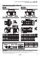


∗ This figure shows the recommended
machining dimensions of
the mounting surface when
viewed from the cylinder side.
Hole Size for Centralised Piping on the Bottom(Machine the mounting side to the dimensions above.)
Bottom ported (ZZ)
(Applicable O-ring)
Centralised piping
Piping tube
O-ring
Operating direction
Operating direction
Centralised
piping
Standard
piping
WXX S
MY1BG
YY
WX SS
WXX
R
øD
d
MY1B
G MY1B
G
1
View A
P(MY1BG)
(Hexagon socket head taper plug)
P
(Hexagon socket
head taper plug)
P
(Hexagon socket
head taper plug)
G
PP QQ
SMC
B
RR
TT
P
(Hexagon socket head taper plug)
Z + Stroke
A
P
(Port)
G
PP
PD
PC
2 x øT counterbore depth E
Floating bracket mounting thread
(2 x
JJ thread depth from bottom of counterbore KK)
YH
NF
QQPP
G
N
P
(Port)
SMC
A
H
LW
NE
NH
SSRR
TT UU
P(MY1BG)
(Hexagon socket
head taper plug)
P
(Port)
P
(Port)
ZZ
(Hexagon socket head taper plug)
XX
XXX
(WW)
ZZ(MY1BG)
(Hexagon socket head taper plug)
2 x 2 x J depth K
VVZZ
(Hexagon socket head taper plug)
VV
(WW) XXX
P
(Hexagon socket
head taper plug)
(
LL
)
L
PA
2 x 2 x ø
B counterbore depth C
øLD through-hole
4 x MM depth M
YW
NW
QW
NC
Cushion needle
GB
Q + StrokePG
PB
View B
P
(Hexagon socket head taper plug)
G
RR
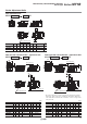
Standard/Centralised Piping Type ø25, ø32, ø40
Note) Refer to the “Bottom Ported” on the left.
Port VariationsBottom Ported
Port variations
L R
L R
Head cover piping connection can be freely
selected to best suit different piping conditions.
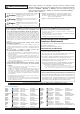
ABC GGBH KJLDL LL LW M MM N NC
Model
110
140
170
9
11
14
5.5
6.6
8.5
16
19
23
24.5
28.5
35
54
68
84
9.5
16
15
M6 x 1
M8
x
1.25
M10
x
1.5
5.6
6.8
8.6
110
140
170
55
70
85
42
52
64
9
12
12
M5 x 0.8
M6 x 1
M6 x 1
30
37
45
18
22
26.5
MY1B25
MY1B32
MY1B40
NE NF
40.2
50.2
62.7
40.5
50
62
NH
39
49
61.5
NW
53
64
75
JJ
M5 x 0.8
M5 x 0.8
M6 x 1
KK
9
10
13
E
2
2
2
PPAPB QPP RRQW T TT WW XXX YH Z
ZZ
Model
Model
Rc1/8
Rc1/8
Rc1/4
60
80
100
30
35
40
206
264
322
12
16
18.5
15
16
23.5
42
51
59
10
10
14
14.5
16
20
11
12
14
15.5
20
23.5
38.5
48
60.5
220
280
340
Rc1/16
Rc1/16
Rc1/8
MY1B25
MY1B32
MY1B40
YW
46
55
67
MY1B25
MY1B32
MY1B40
UU
18
32
35
QQ
16
16
24
PC
55
70
85
PD
6
10
12
PG
7
8
9
XX
26.5
40
47
SS
6
11
12
VV
23.3
28.5
35
[mm]
WXX Y
SdDR
Applicable O-ring
Model
15.5
20
23.5
16.2
20.4
25.9
5.5
5.5
6
6
6
8
11.4
11.4
13.4
1.1
1.1
1.1
MY1B25
MY1B32
MY1B40
C9
C11.2
Standard piping/Centralised piping
[mm]
WX
SS
Model
26.5
40
47
10
5.5
6
MY1B25
MY1B32
MY1B40
Centralised piping
[mm]
L
L
L
L
L
L
L
L
R
R
R
R
R
R
R
R
R
R
R
R
Standard piping/Centralised piping
Centralised piping
MY1B25 /32 /40 Z
Stroke
Series MY1B
10