
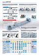
Brochure


25 32 40
Options
Theoretical Output
1.14
2.28
3.11
0.11
0.17
0.25
0.02
0.02
0.04
0.06
0.12
0.23
0.10
0.21
0.32
0.18
0.40
0.49
Unit: kg
Weight
0.2
98
161
251
0.3
147
241
377
0.4
196
322
502
0.5
245
402
628
0.6
294
483
754
0.7
343
563
879
0.8
392
643
1005
Component Parts
MY-A25L2
Without Spacer
MY-A25L2-6
With short spacer
MY-A25L2-7
With long spacer
MY-A25L2-6N
Short spacer only
AMY
L2
25 6N
Stroke adjustment unit
Bore size
25
32
40
25 mm
32 mm
40 mm
Unit no.
A1
A2
L1
L2
H1
H2
Stroke adjustment unit
A unit
L unit
H unit
Symbol
Mounting position
Left
Right
Left
Right
Left
Right
Intermediate fixing spacer
—
Without Spacer
Spacer delivery style
—
N
Unit installed
Spacer only
∗Spacers are used to fix the stroke adjustment unit at an
intermediate stroke position.
∗Spacers are shipped for a set of two.
Stroke adjustment unit
Intermediate fixing spacer
Spacer length
Short spacer
Long spacer Long spacer
Note) For details about adjustment range,
refer to page. 6.
Short spacer
MY-A25L2-7N
Long spacer only
Short spacer
Long spacer
6
7
Stroke Adjustment Unit/Part No.
Unit: N
Operating pressure [MPa]
25
32
40
Bore size
[mm]
Piston area
[mm
2
[
490
804
1256
Note) Theoretical output [N] = Pressure [MPa] x Piston area [mm
2
]
Bore size
[mm]
25
32
40
Basic
weight
Additional
weight per
50 mm
of stroke
Side support
weight
(per set)
A/B type weight
Stroke adjustment unit weight
(per unit)
A unit
weight
L unit
weight
H unit
weight
Calculation: (Example) MY1B25-300AZ
Basic weight ·························· 1.14 kg
Cylinder stroke ······················ 300 mm stroke
Additional weight ··················· 0.11 kg/50 mm stroke
A unit weight ·························· 0.06 kg
1.14 + 0.11 x 300 ÷ 50 + 0.06 x 2 ≈ 1.92 kg
Side support A
Side support B
MY-S25A
MY-S25B
MY-S32A
MY-S32B
Type
Side Support/Part No.
Bore size
[mm]
For details about the dimensions, etc., refer to page 12.
Side supports consist of a set of right and left supports.
Series MY1B
Mechanically Jointed Rodless Cylinder
Basic Type
7