Air Cylinder New ø20, ø25, ø32, ø40, ø50, ø63, ø80, ø100 Female rod end available as standard RoHS Selectable Rod end styles suitable for the application can be selected. Female thread Easy fine adjustment of auto switch position Fine adjustment of the auto switch position is possible by simply loosening the screw attached to the auto switch. Transparent switch bracket improves visibility of indicator LED.
Air Cylinder Part numbers with rod end bracket and/or pivot bracket available Not necessary to order a bracket for the applicable cylinder separately Note) Mounting bracket is shipped together with the product, but not assembled. Example) CDG1 D N20-50Z- N W -M9BW Mounting Pivot bracket — None N Pivot bracket is shipped together with the product, but not assembled.
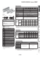
Series CG1 Stroke Variations [mm] Standard stroke Bore size [mm] 20 50 75 100 125 150 200 250 300 20 25 32 40 50 63 80 100 Series Variations Series CG1-Z Series Action Rod 20 Standard Variations Bore size [mm] Cushion 25 32 40 50 63 80 100 With Clean Air-hydro rod boot series Page Rubber bumper CG1-Z Double Single rod acting Page 1 Air cushion Double Double rod acting Rubber bumper Page 18 Air cushion Single rod Single Rubber (Spring return acting bumper /extend) Non-rotati
Combinations of Standard Products and Made to Order Specifications Series CG1 : Standard : Made to Order : Special product (Please contact SMC for details.
CG1R (Direct mount type) Double acting — — — — — — — — — — — — — — — — — — — — — XC8 — XC9 — — XC10 XC27 — — — — XC29 Standard 10- Note 2) Note 2) XB6 D CG1쏔-쏔JK CG1쏔H 20- Note 9) CG1쏔RV XB7 XB9 XB13 XC4 XC6 Note 2) XC11 XC12 XC13 XC20 XC22 XC35 XC37 XC42 Auto Switch Long st XC85 X446 Made to Order — — CG1W —
Air Cylinder: Standard Type Double Acting, Single Rod Series CG1 RoHS ø20, ø25, ø32, ø40, ø50, ø63, ø80, ø100 How to Order With auto switch CG1 B N 20 100 Z CDG1 D N 20 100 Z N W M9BW With auto switch (Built-in magnet) Pivot bracket Bore size Mounting — 20 20 mm 25 25 mm 32 32 mm 40 40 mm 50 50 mm 63 63 mm 80 80 mm 100 100 mm Basic B Z∗ Basic (without trunnion mounting female thread) Axial foot L Rod flange F Head flange G Rod trunnion U∗ Head trunnion T∗ Clevis D N N A — Rc ø20 to ø10
Piston speed 50 to 1000 mm/s Up to 1000 st 0 mm, Up to 1500 st Rubber bumper, Air cushion Cushion (For details, refer to pages 49 to 65.) Rubber bumper Air cushion Male rod end 0.28 0.41 0.66 1.20 2.00 3.40 5.90 9.90 Female rod end 0.11 0.18 0.29 0.52 0.91 1.54 2.71 4.54 R: 0.35 R: 0.56 Male rod end H: 0.42 H: 0.65 0.91 1.80 3.40 4.90 11.80 16.70 Female rod end 0.29 0.52 0.91 1.54 2.71 4.54 0.11 0.
Series CG1 Rod Boot Material Ordering Example of Cylinder Assembly Clevis Cylinder model: CDG1DN20-100Z-NW-M9BW Auto switch Maximum operating temperature Symbol Rod boot mater J K Nylon tarpaulin 70°C Heat resistant tarpaulin 110°C∗ ∗ Maximum ambient temperature for the rod boot itself. Mounting D: Clevis Pivot bracket N: Yes Rod end bracket W: Double knuckle joint Auto switch D-M9BW: 2 pcs.
Double Acting, Single Rod 0.11 0.11 0.21 0.18 0.12 0.17 0.08 0.05 0.05 0.05 0.01 0 −0.01 0.17 0.17 0.29 0.26 0.19 0.25 0.09 0.09 0.09 0.07 0.01 0.01 −0.02 0.24 0.25 0.40 0.38 0.28 0.39 0.17 0.09 0.09 0.09 0.01 0.04 −0.02 0.44 0.45 0.67 0.65 0.49 0.68 0.25 0.10 0.13 0.14 0.01 0 −0.05 0.79 0.80 1.26 1.16 0.88 1.19 0.44 0.22 0.26 0.21 0.01 0.01 −0.10 1.06 1.09 1.77 1.64 1.20 1.78 0.80 0.22 0.26 0.25 0.02 0.04 −0.10 2.07 — 3.04 2.78 — 2.77 0.98 0.39 0.64 0.35 0.02 0 −0.19 3.16 — 4.91 4.44 — 4.44 1.75 0.
CG1 Series Water Resistant CDG1 Mounting style Type Bore size Port thread type R Stroke Z Be sure to read before handling. Refer to back cover for Safety Instructions. For Actuator and Auto Switch Precautions, refer to “Handling Precaution for SMC Products” and the Operation Manual on SMC website, http://www.smcworld.
Double Acting, Single Rod u Long stroke 1001 to 1500 Single Acting, Spring Return/Extend Long stroke With air cushion !0 r @0 t @2 q !6 w !1 e @1 o !3 !7 !2 @3 !4 !9 @2 !8 Non-rotating Rod !5 Long stroke Component Parts Material Aluminium alloy Note Hard Anodised 2 Tube cover Aluminium alloy Hard Anodised 3 Piston Aluminium alloy 4 Piston rod Stainless steel Carbon steel∗ 5 Bushing Bearing alloy 6 Bumper Resin 7 Bumper Resin 8 Retaining ring Stainless steel 9 Wear rin
Series CG1 Basic: CG1BN H1 TA 4 x TC GB øE 0 0 −0.05 øI øE−0.05 øTD C MM 2xP (Rc, NPT, G) øD 2 x TC GA R0 .4 F Width across flats KA R0 .4 Width across flats B1 AL A TE TG TF K H F S + Stroke ZZ + Stroke NA 8xJ C NA TB TC thread detail With air cushion WA GA 2xP (Rc, NPT, G) Cushion valve, Width across flats WH WB GB 10° Wθ° Basic (No Trunnion Mounting Female Thread): CG1ZN .4 øE 0 øI øE−0.05 øD H1 0 −0.
Double Acting, Single Rod 30 30 35 35 40 40 52 62 18 19 19 19 19 20 10 7 55 62 62 70 78 78 80 80 27 32 38 48 59 72 59 71 15.5 16.5 18.5 21.5 24 24 — — 10.5 10.5 10.5 10.5 10.5 10.5 — — ZZ 126 (134) 133 (141) 135 (143) 150 (159) 170 (182) 170 (182) 191 (205) 191 (205) H ZZ + Stroke [mm] Bore size A1 H MM ZZ 20 25 32 40 50 63 80 100 8 8 12 13 18 18 21 25 13 14 14 15 16 16 19 22 M4 x 0.7 M5 x 0.8 M6 x 1 M8 x 1.25 M10 x 1.5 M10 x 1.5 M14 x 1.5 M16 x 1.
Series CG1 Axial Foot: CG1LN S + Stroke H Width across flats KA Width across flats NA GB 8xJ H1 Width across flats B1 AL A K Z W X 2 x øLC Y (Knock pin position) LS + Stroke ZZ + Stroke W X Y 2xP (Rc, NPT, G) Cushion valve, Width across flats WH WA GA With air cushion LH LT B C øI øD MM 2xP (Rc, NPT, G) GA M ° 15 C LX LZ 4 x øLD WB GB 10° Wθ° With rod boot h+l h+l 8 8 JH øe øIJ øe øIJ 8 l f Z+l ZZ + l + Stroke l f Z+l ZZ + l + Stroke ø80, ø100 ø20, ø63 GA GB 12
2xP (Rc, NPT, G) Cushion valve, Width across flats WH WB GB Double Acting, Single Rod 10° Wθ° ∗ End boss is machined on the flange for øE. JH øe øIJ øe 8 l f h+l ZZ + l + Stroke l f h+l ZZ + l + Stroke ø20, ø63 Rc, NPT port GA GB 12 12 12 13 14 14 20 20 10 (12) 10 (12) 10 (12) 10 (13) 12 (14) 12 (14) 16 (20) 16 (20) P GA GB P 1/8 1/8 1/8 1/8 1/4 1/4 3/8 1/2 12 12.5 10.5 13 14 14 17.5 17.5 10 (12) 10 (12.5) 10 (10.5) 10 (10) 12 (14) 12 (14) 16 (17.5) 16 (17.5) M5 x 0.8 M5 x 0.
CG1 Series Head Flange: CG1GN F Width across flats KA H1 GB 2xP (Rc, NPT, G) .4 0 øI øE−0.05 B FX±0.15 C MM GA 0 ∗øE−0.05 8xJ øD 4 x øFD R0 Width across flats B1 AL A C FX±0.15 B Width across flats NA K H S + Stroke ZZ + Stroke FT F ∗ End boss is machined on the flange for øE.
Series CG1 S + Stroke GB 2 x øTDe8 (Pin O.D) øE−0.05 h+l f JH øe [mm] GA GB 12 12 12 13 14 14 10 (12) 10 (12) 10 (12) 10 (13) 12 (14) 12 (14) [mm] Bore TA size 20 11 25 11 32 11 40 12 50 13 63 13 TDe8 −0.025 −0.047 −0.025 −0.047 −0.032 −0.059 −0.032 −0.059 −0.032 −0.059 −0.032 −0.059 8 10 12 14 16 18 TR TZ Z ZZ 39 43 54.5 65.5 80 98 46 51 51 62 71 71 106 (114) 111 (119) 113 (121) 130 (139) 150 (162) 150 (162) 47.6 53 67.7 78.7 98.6 119.2 P G port GA GB P 1/8 12 10 (12) M5 x 0.
CG1 Series Head Trunnion: CG1TN S + Stroke H K F F 2xP (Rc, NPT, G) GA GB øE−0.05 0 R0 .4 0 øI øE−0.05 øD MM ∗ 2 x øTDe8 (Pin O.D) A AL H1 R0 .4 TR Width across flats B1 Width across flats KA Width across flats NA Z + Stroke ZZ + Stroke TZ TB ∗ Constructed of a trunnion pin, flat washer and hexagon socket head cap bolt.
Series CG1 H 2xP (Rc, NPT, G) GA JH JW Direct Mount f l Z + l + Stroke ZZ + l + Stroke [mm] GA GB 12 12 12 13 14 14 10 (12) 10 (12) 10 (12) 10 (13) 12 (14) 12 (14) G port P GA 1/8 1/8 1/8 1/8 1/4 1/4 12 12.5 10.5 13 14 14 [mm] Applicable TT TZ Z ZZ pin part no. 3.2 43.4 118 (126) 129 (137) CD-G02 3.2 48 125 (133) 138 (146) CD-G25 4.5 59.4 131 (139) 146 (154) CD-G03 4.5 71.4 150 (159) 168 (177) CD-G04 6 86 173 (185) 193 (205) CD-G05 8 105.4 178 (190) 200 (212) CD-G06 GB P 10 (12) M5 x 0.
Series CG1 Clevis: CG1DN (ø80, ø100) S + Stroke H TZ CZ C F A AL H1 K L V GB 2xP (Rc, NPT, G) RR øCDH10 (Hole dia.) d9 (Shaft dia.) R0 .4 C 0 øI øE−0.05 øD MM GA +0.5 8xJ CX +0.
Double Acting, Single Rod TE TF TH TS TT TV TW TX TY Z Bore size Z 20 25 32 40 50 63 38 45.5 54 63.5 79 96 10 10 10 10 20 20 5.5 5.5 6.6 6.6 9 11 25 30 35 40 50 60 28 33 40 49 60 74 3.2 3.2 4.5 4.5 6 8 35.8 39.8 49.4 58.4 72.4 90.4 42 42 48 56 64 74 16 20 22 30 36 46 28 28 28 30 36 46 46 51 51 62 71 71 20 25 32 40 50 63 24 25 25 27 29 29 TX TV TY TW 4 x øTF +0.
Series CG1 Dimensions of Accessories Single Knuckle Joint Double Knuckle Joint I-G02, G03 I-G04, G05, G08, G10 Y-G02, G03 Y-G04, G05, G08, G10 Material: Carbon steel Material: Cast iron Material: Carbon steel Material: Cast iron ø Part no. I-G02 I-G03 I-G04 I-G05 I-G08 I-G10 Applicable bore size [mm] 20 25,32 40 50,63 80 100 A A1 E1 L1 34 41 42 56 71 79 8.5 10.5 14 18 21 21 첸16 첸20 ø22 ø28 ø38 ø44 25 30 30 40 50 55 MM R1 U1 NDH10 M8 x 1.25 M10 x 1.25 M14 x 1.5 M18 x 1.5 M22 x 1.
Double Acting, Single Rod Note) In the case of w/rod boot, Without rod boot and a foot bracket or rod Nylon tarpaulin One J flange as a bracket, those end K Heat resistant tarpaulin parts are to be assembled at the time of shipment. Nylon tarpaulin Both JJ ends KK Heat resistant tarpaulin ∗ For female rod end, no rod — 20 mm 25 mm 32 mm 40 mm 50 50 mm 63 63 mm 80 80 mm 100 100 mm boot is provided.
Series CG1W Specifications 20 Bore size [mm] 25 32 Action 40 50 63 80 100 Double acting, Double rod Lubricant Not required (Non-lube) Fluid Air Proof pressure 1.5 MPa Maximum operating pressure 1.0 MPa Minimum operating pressure 0.08 MPa Ambient and fluid temperature Without auto switch: −10°C to 70°C (No freezing) With auto switch : −10°C to 60°C Piston speed 50 to 1000 mm/s Up to 1000 st 0 mm, Up to 1500 st Rubber bumper, Air cushion Cushion Allowable kinetic energy [J] +1.
0.13 0.22 0.33 0.55 1.02 1.37 2.64 4.09 Axial foot 0.24 0.35 0.49 0.77 1.50 2.09 3.60 5.84 Flange 0.21 0.32 0.47 0.75 1.36 1.87 3.35 5.44 Trunnion 0.14 0.24 0.36 0.60 1.16 1.51 — — Pivot bracket 0.08 0.09 0.17 0.25 0.44 0.80 — — Single knuckle joint 0.05 0.09 0.09 0.10 0.22 0.22 0.39 0.57 Double knuckle joint (with pin) 0.05 0.09 0.09 0.13 0.26 0.26 0.64 1.31 Additional weight per 50 mm of stroke 0.07 0.10 0.13 0.23 0.34 0.38 0.54 0.
Series CG1W Construction With rubber bumper ø80, ø100 y i r !2 t !4 q w y !3 eu With air cushion i r !2 t !4 q !1 w o !3 e Component Parts No.
Series CG1W Width across flats KA øE−0.05 H l f h+l ZZ + l + Stroke ZZ + 2 Stroke 8 8 8 JH øe øIJ 8 Non-rotating Rod f l + Stroke h + l + Stroke S + Stroke ZZ + 2 ( l + Stroke) JW [mm] Bore size TA TC∗∗ 20 25 32 40 50 63 80 100 11 11 11 12 13 13 — — M5 x 0.8 M6 x 0.75 M8 x 1.0 M10 x 1.25 M12 x 1.25 M14 x 1.5 — — A AL B1 C D E F GA H1 I 18 22 22 30 35 35 40 40 15.5 19.5 19.5 27 32 32 37 37 13 17 17 19 27 27 32 41 14 16.
Series CG1W Basic with Air Cushion: CG1WBA Width across flats KA 8xJ WA GA F MM H1 øE−0.05 R0 .4 0 0 AL A .4 R0 Width across flats B1 10° Wθ° Width across flats KA øI øD H1 Cushion valve, Width across flats WH øE−0.05 MM 2xP (Rc, NPT, G) C WA F GA øD 10° Wθ° K TA 4 x TC H AL K A H + Stroke TA S + Stroke ZZ + 2 Stroke Width across flats B1 C NA For the one with rod boot, refer to w/rubber bumper.
0 øE−0.05 H FX±0.15 B 2 x øTDe8 (Pin O.D) Trunnion: CG1WU첸 Bracket mounting range ∗ 4 x øTF ø Trunnion Bore size 20 25 32 40 50 63 Stroke range B Up to 1500 38 Up to 1500 45.5 Up to 1500 54 Up to 1500 63.5 Up to 1500 79 Up to 1500 96 TDe8 −0.025 −0.047 −0.025 −0.047 −0.032 −0.059 −0.032 −0.059 −0.032 −0.059 −0.032 −0.059 8 10 12 14 16 18 10 10 10 10 20 20 5.5 5.5 6.6 6.6 9 11 25 39 28 30 43 33 35 54.5 40 40 65.
Air Cylinder: Standard Type Single Acting, Spring Return/Extend Series CG1 ø20, ø25, ø32, ø40 How to Order CG1 L N 25 100 S With auto switch Z CDG1 L N 25 100 S Z M9BW With auto switch Number of auto switches (Built-in magnet) Mounting B Basic Z Basic (without trunnion mounting female thread) L F Axial foot Rod flange G U T D — S n Head flange Rod trunnion Head trunnion Clevis Auto switch Rod end thread ∗ Mounting bracket is shipped together with the product, but not assembled.
Double Acting, Single Rod 40 Air Proof pressure 1.5 MPa Maximum operating pressure 1.0 MPa 0.18 MPa Ambient and fluid temperature 0.23 MPa Standard Minimum operating pressure Without auto switch: –10°C to 70°C (No freezing) With auto switch : –10°C to 60°C 50 to 1000 mm/s Stroke length tolerance Up to 200 st +1.
Series CG1 Weights Spring return Basic weight Mounting bracket weight Spring extend [kg] 20 Bore size [mm] 25 st 25 32 40 0.17 0.27 0.40 0.63 50 st 0.19 0.30 0.45 0.71 75 st 0.26 0.40 0.58 0.91 100 st 0.28 0.43 0.62 0.99 125 st 0.35 0.53 0.76 1.20 150 st — 0.56 0.81 200 st — 0.69 Axial foot 0.11 Flange [kg] 20 Bore size [mm] 25 st 25 32 40 0.16 0.25 0.38 0.59 50 st 0.18 0.28 0.43 0.67 75 st 0.24 0.37 0.54 0.83 100 st 0.26 0.40 0.58 0.
Air Cylinder: Standard Type Single Acting, Spring Return/Extend CG1 Series GB .4 R0 R0 .4 K TA 4 x TC TB H F S + Stroke Width across flats KA F GA RcP GB Plug with fixed orifice .4 Non-rotating Rod thread depth A1 H ZZ + Stroke Bore size TA 20 25 32 40 11 11 11 12 A AL B1 C D E F GA GB H H1 I J K KA MM NA P 18 22 22 30 15.5 19.5 19.5 27 13 17 17 19 14 16.
Series CG1 With Mounting Bracket Rod flange: CG1FN [mm] FT Stroke Bore size B E F FX range Up to 125 40 12 2 28 20 Up to 200 44 14 2 32 25 Up to 200 53 18 2 38 32 Up to 200 61 25 2 46 40 ∗ End boss is machined on the flange for øE. ∗ Other dimensions are the same as basic type. 4 x øFD 0 øE−0.05 B FX±0.15 F H FX±0.15 B Rod Flange Bore size Head flange: CG1GN B FX±0.15 0 øE−0.05∗ 4 x øFD 20 25 32 40 FT H FX±0.15 B F ZZ + Stroke 20 25 32 40 FT H 5.5 5.5 6.6 6.
Double Acting, Single Rod Type Basic (without trunnion Z∗ mounting female thread) L F G U T D Axial foot Rod flange Head flange Rod trunnion Head trunnion Clevis N Rubber bumper A Air cushion (ø40 to ø63 only) Auto switch — Bore size Note) Mounting bracket is shipped together with the product, but not assembled. ∗ The cylinder for F, G, L, D mounting types is Z: Basic (without trunnion mounting female thread).
CG1K Series Specifications 20 Bore size [mm] 25 Action 32 Lubricant 1.5 MPa Maximum operating pressure 1.0 MPa Minimum operating pressure 0.05 MPa Ambient and fluid temperature Air cushion Made to Order Without auto switch: –10°C to 70°C (No freezing) With auto switch : –10°C to 60°C Piston speed 50 to 500 mm/s Stroke length tolerance +1.
Air Cylinder: Non-rotating Rod Type Double Acting Series CG1K Single Acting, Spring Return/Extend ø20 to ø32 With air cushion o r !8 t q @0 !3 !5 w e!9 i!0 !4 @1 !1 !7 @0 !6 Non-rotating Rod !2 Long stroke Replacement Parts/Seal Kit Material Aluminium alloy Note Hard Anodised 2 Tube cover Aluminium alloy Hard Anodised 3 Piston Aluminium alloy 4 Piston rod Stainless steel Carbon steel∗ 5 Non-rotating guide 6 Bumper Resin 7 Bumper Resin 8 Wear ring 9 Rod end nut Carbon
Series CG1K Basic With rubber bumper Width across flats KA ø20 to ø63 F GA H1 .4 R0 C øE−0.05 0 Width across flats B1 4 0 øE−0.05 øI øD MM GB 2 x RcP R0 . AL TA A 4 x TC H TB S + Stroke F C NA 8xJ ZZ + Stroke With air cushion ø40 to ø63 WA F GA H1 .4 With Air Cushion øE−0.05 øI øD R0 Width across flats B1 Bore size WA WB 40 50 63 17 18 18 15 (17) 16 (18) 17 (18) .4 0 0 øE−0.
Double Acting, Single Rod With auto switch — Type N Rubber bumper 20 25 32 40 50 63 20 mm 25 mm Cylinder stroke [mm] Refer to “Standard Strokes” on page 35. Built-in Magnet Cylinder Model 32 mm If a built-in magnet cylinder without an auto switch is required, there is no need to enter the symbol for the auto switch. (Example) CDG1KWFN32-100Z 40 mm 50 mm 63 mm Non-rotating Rod Bore size ∗ Mounting bracket is shipped together with the product, but not assembled.
Series CG1KW Specifications 20 Bore size [mm] 25 Action 32 40 50 63 Double acting, Double rod Lubricant Not required (Non-lube) Fluid Air Proof pressure 1.5 MPa Maximum operating pressure 1.0 MPa Symbol Minimum operating pressure 0.08 MPa Rubber bumper Ambient and fluid temperature Without auto switch: –10°C to 70°C (No freezing) With auto switch : –10°C to 60°C Piston speed 50 to 500 mm/s Stroke length tolerance Up to 1000 st Cushion +1.4 0 mm, Up to 1500 st +1.
Double Acting, Single Rod y Standard Single Acting, Spring Return/Extend u Component Parts Replacement Parts/Seal Kit Description Rod cover A Material Aluminium alloy Note Hard Anodised 2 Rod cover B Aluminium alloy Hard Anodised 3 Cylinder tube Aluminium alloy Hard Anodised 4 Piston Aluminium alloy 5 Piston rod A Stainless steel Carbon steel∗ ø32 or smaller Hard chrome plating∗ ø40 or larger 6 Piston rod B Stainless steel Carbon steel∗∗ For ø20 or ø25 with built-in magnet Hard c
CG1KW Series Basic with Rubber Bumper: CG1KWBN Width across flats KB 2 x RcP GA F Width across flats KA F GA MM MM C 0 0 øE−0.05 øE−0.05 øI øD H1 øD H1 .4 .4 R0 Width across flats B1 R0 AL A 4 x TC TA TA K H + Stroke S + Stroke ZZ + 2 Stroke H AL A Width across flats B1 C 8xJ NA [mm] AL B1 C D DK Up to 1500 18 15.5 13 14 8 9.2 12 2 12 Up to 1500 22 19.5 17 16.5 10 11 14 2 12 Up to 1500 22 19.5 17 20 12 12 18 2 12 6 38 M5 x 0.8 depth 8 5.
Double Acting, Single Rod Type Rubber bumper Air cushion If a built-in magnet cylinder without an auto switch is required, there is no need to enter the symbol for the auto switch. (Example) CDG1RA32-100Z — F — S n Male rod end Female rod end 32 mm 40 mm 2 pcs. 1 pc. “n” pcs. Auto switch 50 mm — 63 mm Without auto switch ∗ For applicable auto switches, refer to the table below. Cylinder stroke [mm] Refer to “Standard Strokes” on page 39. Made to Order For details, refer to page 39.
Series CG1R Specifications The CG1R direct mount cylinder can be installed directly through the use of a square rod cover. Bore size [mm] 20 25 Action 32 40 50 63 Double acting, Single rod Lubricant Not required (Non-lube) Fluid Air Space-saving is granted. Proof pressure Because it is a directly mounted style without using brackets, its overall length is shorter, and its installation pitch can be made smaller.
Double Acting, Single Rod iu Single Acting, Spring Return/Extend Standard i !2 !6 !1 @0 !3 Component Parts Description Rod cover Material Aluminium alloy Note Hard Anodised No.
Series CG1R Basic with Bottom Mounting With rubber bumper X Width across flats KA GA 2 x øLD GB H1 .4 L 0 øE−0.05 øI øD R0 LH MM 2 x RcP Width across flats B1 AL A Y LX N L K H S + Stroke F ZZ + Stroke WA GA With air cushion Width across flats KA 10° MM 2xP X Cushion valve, Width across flats WH 2 x øLD WB WC GB H1 .4 øI øD R0 LH L 0 øE−0.
Series CG1 16 B ( ): Dimension of the D-A96 A and B are the dimensions from the end of the head cover/rod cover to the end of the auto switch. D-A9쏔V ø20 to ø63 16 ≈Hs 16 ≈Hs D-G5/K5/G5쏔W/G5BA D-K59W, D-G59F, D-G5NT ø20 to ø100 A and B are the dimensions from the end of the head cover/rod cover to the end of the auto switch. D-C7/C8, D-C73C/C80C ø20 to ø63 ≈Hs ≈Hs 16 24.5 A A B D-H7쏔/H7쏔W D-H7NF/H7BA/D-H7C ø20 to ø63 B ≈Hs 16 24.
Series CG1 Auto Switch Proper Mounting Position (Detection at stroke end) Auto Switch Proper Mounting Position/Except Single Acting and Direct Mount Type (CG1R) Auto switch D-M9쏔 model D-M9쏔V Bore size D-M9쏔W D-M9쏔WV D-M9쏔A D-M9쏔AV A B 24 (32) 24.5 (32.5) 25 (33) 27 (36) 32 (44) 33.5 (45.5) D-H7쏔W D-H7NF D-H7BA D-H7쏔 D-H7C D-A9쏔 D-A9쏔V A B 20 (28) 20.5 (28.5) 21 (29) 23 (32) 28 (40) 29.5 (41.5) A D-G5쏔/K59 D-G5쏔W/K59W D-B5쏔 D-G59F D-B64 D-G5NT D-G5BA D-C7쏔 D-C80 D-C73C D-C80C B A 19.5 (27.
D-C7쏔 D-C80 D-C73C D-C80C D-G5NT D-G59F D-B5쏔 D-B64 D-B59W Auto Switch Proper Mounting Position (Detection at stroke end) Auto Switch Proper Mounting Position/Direct Mount Type (CG1R) Bore size 20 25 32 40 50 63 D-M9쏔W D-M9쏔WV D-M9쏔A D-M9쏔AV A B D-H7쏔W D-H7NF D-H7BA D-H7쏔 D-H7C D-A9쏔 D-A9쏔V A D-C7쏔 D-C80 D-C73C D-C80C B A D-G59F D-G5NT D-B5쏔 D-B64 A Double Acting, Single Rod D-B59W A B B A B 12 24 8 20 7.5 19.5 8.5 20.5 4 16 2.5 14.5 5.5 17.5 11.5 24.5 7.5 20.
Series CG1 Minimum Stroke for Auto Switch Mounting n: Number of auto switches [mm] Auto switch model Number of auto switches With 2 pcs. With 1 pc. Different surfaces Same surface With n pcs.
Double Acting, Single Rod 100 — — — — D-C7쏔/C80 D-C73C/C80C BMA2-020A BMA2-025A BMA2-032A BMA2-040A BMA2-050A BMA2-063A D-H7쏔 (A set of band and screw) (A set of band and screw) (A set of band and screw) (A set of band and screw) (A set of band and screw) (A set of band and screw) D-H7쏔W D-H7NF — — BMA2-020AS BMA2-025AS BMA2-032AS BMA2-040AS BMA2-050AS BMA2-063AS (A set of band and screw) (A set of band and screw) (A set of band and screw) (A set of band and screw) (A set of band and screw) (A set
Series CG1 Operating Range [mm] Bore size Auto switch model D-M9쏔(V) D-M9쏔W(V) D-M9쏔A(V) D-A9쏔 D-C7/C80 D-C73C/C80C D-B5쏔/B64 D-B59W D-H7쏔/H7쏔W D-H7NF/H7BA D-H7C D-G5쏔/G5쏔W/G59F D-G5BA/K59/K59W D-G5NT D-G5NB 20 25 32 40 50 63 80 100 4.5 5.0 4.5 5.5 5.0 5.5 — — 7 6 8 8 8 9 — — 8 10 9 10 10 11 — — 8 10 9 10 10 11 11 11 13 13 14 14 14 17 16 18 4 4 4.5 5 6 7 8.5 9 4 4 4.5 4 4 35 40 10 5 4.5 40 9.5 6 5 6 45 45 6.5 — — 10.5 — — 6.
Prior to Use Source Input Specifications 3-wire, NPN 3-wire, PNP Auto switch Blue COM COM (PLC internal circuit) 2-wire Brown Input (PLC internal circuit) Standard Blue Brown COM Auto switch Auto switch Blue Input (PLC internal circuit) (PLC internal circuit) Connect according to the applicable PLC input specifications, as the connection method will vary depending on the PLC input specifications.
Series CG1 Simple Specials/Made to Order Please contact SMC for detailed specifications, delivery and prices. 왎 Simple Specials The following special specifications can be ordered as a simplified Made-to-Order. There is a specification sheet available on paper and CD-ROM. Please contact your SMC sales representatives if necessary.
Page CG1R Page Page 53 Page 53 Page 54 Page 54 CG1 Single Acting, Spring Return/Extend Page 53 Page 58 Page 59 Page 59 to 61 Page 62 Page 62 Page 62 Page 63 Page 63 Page 63 Page 64 CG1K Page 57 CG1KW Page 56 CG1R Page 55 Double Acting, Single Rod Page 54 Non-rotating Rod Page 65 Auto Switch Page 65 Made to Order Double rod Rubber (Direct mount type) Double acting Single rod Rubber Air Direct Mount CG1K (Non-rotating rod type) Double acting Single rod Rubber Air Standard Page 51 Dou
Series CG1 Simple Specials These changes are dealt with Simple Specials System. 1 Change of Rod End Shape Applicable Series Series Standard type CG1-Z Symbol for change of rod end shape Action CG1 Double acting, Single rod XA0 to 30 CG1W Double acting, Double rod XA0 to 30 Non-rotating rod type CG1K Double acting, Single rod XA0 to 30 Direct mount type CG1R Double acting, Single rod XA0 to 30 Note Precautions 1.
H MM W Symbol: A26 MM A AL H LK H øDA LB K H 30n Symbol: A30 W L T AL A 30n MM L H MM T A H CG1 30n Made to Order A CG1W A H W 30n MM L AL Symbol: A29 øDA Auto Switch AL H Symbol: A27 øDA 30n MM MM 30n B A C H Symbol: A25 Symbol: A28 øRD L øDB T A T A LK H Symbol: A24 30n Direct Mount A MM CG1KW 30n øDB MM Symbol: A23 CG1R Symbol: A22 øDA 30n H H Symbol: A21 MM A A H Symbol: A20 Single Acting, Spring Return/Extend Standard H 30n MM Doub
Series CG1 Made to Order Please contact SMC for detailed dimensions, specifications and lead times. Symbol 1 Heat Resistant Cylinder (–10 to 150°C) -XB6 Air cylinder which changed the seal material and grease, so that it could be used even at higher temperature up to 150 from −10°C. Applicable Series Series Description Model Standard CG1-Z type Specifications Action Note Except with auto switch. Double acting, CG1 Cylinders with rubber bumper Single rod have no bumper.
Double Acting, Single Rod Even if driving at lower speeds 10 to 50 mm/s, there would be no stick-slip phenomenon and it can run smoothly. Specifications Model CG1-Z Standard type CG1 Action Note Double acting, Single rod Except with rod boot and with air cushion Note 1) Operate without lubrication from a pneumatic system lubricator. Note 2) For speed adjustment, use speed controllers for controlling at lower speeds.
Series CG1 Symbol 7 Adjustable Stroke Cylinder/Adjustable Extension Type -XC8 It adjusts the extending stroke by the stroke adjustable mechanism equipped in the head side.
Double Acting, Single Rod CG1 Double acting, Single rod Except clevis type and with air cushion Stroke adjustment symbol Stroke adjustment range [mm] CG1K Double acting, Except head flange and clevis types Single rod and with air cushion CG1R Double acting, Single rod Additional specifications A 0 to 25 B 0 to 50 Same as standard type Except with air cushion How to Order CG1 Mounting style Type Bore size ∗ Except clevis type Stroke Stroke adjustment symbol Z XC9 Adjustable stroke cylinder/
CG1 Series Symbol 9 Dual Stroke Cylinder/Double Rod Type -XC10 Two cylinders are constructed as one cylinder in a back-to-back configuration allowing the cylinder stroke to be controlled in three steps.
Double Acting, Single Rod -XC11 Two cylinders can be integrated by connecting them in line, and the cylinder stroke can be controlled in two stages in both directions. Specifications: Same as standard type Applicable Series How to Order CG1 Mounting style Type Bore size ∗ Please contact SMC for each manufacturable stroke length.
Series CG1 Symbol 11 Tandem Cylinder -XC12 This is a cylinder produced with two air cylinders in line allowing double the output force. Applicable Series Specifications: Same as standard type Series Description Model CG1-Z Standard type CG1 Action Note Double acting, Single rod Except with air cushion Function When air pressure is supplied to ports and d , the output force is doubled in the retract stroke. How to Order XC12 Standard model no.
Series CG1 Double Acting, Single Rod Symbol 12 Auto Switch Rail Mounting -XC13 Auto Switch Proper Mounting Position (Detection at stroke end) and Its Mounting Height Series CDG1 Series CDG1R CG1 Made to Order A B A B A B 22.5 (30.5) 30.5 21.5 (29.5) 35.5 26.5 (34.5) 23 (31) 30 22 (30) 35 27 (35) A 30 29.5 B A B 21 (29) 27.5 18.5 (26.5) 21.5 (29.5) 27 19 (27) 32.5 23.5 (31.5) 31.5 22.5 (30.5) 36.5 27.5 (35.5) 31 22 (30) 28.5 19.5 (27.5) 37.5 25.5 (34.5) 36.
Series CG1 Symbol 12 Auto Switch Rail Mounting -XC13 Minimum Stroke for Auto Switch Mounting Operating Range [mm] [mm] Auto switch model D-M9첸/M9첸V D-F7첸V D-J79C D-M9첸WV D-M9첸AV D-F7첸WV D-F7BAV D-A79W D-M9첸W D-M9첸A D-F7첸 D-J79 D-F7첸W/J79W D-F7BA D-F79F/F7NT D-A7첸/A80 D-A7첸H/A80H D-A73C/A80C D-A7첸H D-A80H 1 Number of auto switches n (n: No.
CG1 Double Acting, Single Rod Symbol 13 Head Cover Axial Port -XC20 Head side port position is changed to the axial direction. (Standard head side port is plugged with hexagon socket head screw.) Construction CG1R Double acting, Single rod Except with air cushion How to Order Bore size [mm] 20, 25, 32, 40 50, 63 Head cover axial port Port size Rc1⁄8 Single Acting, Spring Return/Extend XC20 Standard model no. Rc1⁄4 ∗ Same dimensions as standard type except port size.
Series CG1 Symbol 16 Double Knuckle Joint with Spring Pin -XC29 For prevent loosening of the double knuckle joint Applicable Series Specifications: Same as standard type Series Description CG1-Z Standard type Model CG1 Action Double acting, Single rod Dimensions: Same as standard type How to Order Standard model no.
Series CG1 Double Acting, Single Rod Symbol 19 Built-in Shock Absorber in Head Cover Side -XC42 A type of the CG1 series air cylinder in which a special shock absorber is enclosed in the head portion so that its ability to absorb energy during the retraction of the cylinder is considerably greater than the conventional air cushion. Additional specifications Same as standard type ∗ On the axial foot and head flange types, the bracket is mounted at the time of shipment.
Series CG1 Symbol 20 Grease for Food Processing Equipment -XC85 Food grade grease (certified by NSF-H1) is used as lubricant.
Safety Instructions Caution: These safety instructions are intended to prevent hazardous situations and/or equipment damage. These instructions indicate the level of potential hazard with the labels of “Caution,” “Warning” or “Danger.” They are all important notes for safety and must be followed in addition to International Standards (ISO/IEC)∗1), and other safety regulations. Caution indicates a hazard with a low level of risk which, if not avoided, could result in minor or moderate injury.