
Datasheet


39
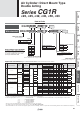
Series CG1R
¡
Basic weight
·············· 0.35
¡
Basic weight
·············· 0.09/50 stroke
¡
Air cylinder stroke
····· 100 stroke
0.35 + 0.09 x 100/50 = 0.53 kg
Note 1) Intermediate strokes not listed above are
produced upon receipt of order.
Manufacture of intermediate strokes at 1
mm intervals is possible. (Spacers are
not used.)
∗
For applicable long strokes, please contact SMC.
∗ A double knuckle joint pin and retaining
rings are shipped together.
[kg]
Calculation (Example) CG1RN32-100Z
(ø32, 100 stroke)
Be sure to read before handling.
Refer to back cover for Safety Instructions. For Actuator and Auto
Switch Precautions, refer to “Handling Precaution for SMC Products”
and the Operation Manual on SMC website, http://www.smcworld.com
When the cylinder is used as mounted with a single side fixed or free, a
bending moment will be applied to the cylinder due to the vibration
generated at the stroke end, and the cylinder may be damaged. In such a
case, mount a bracket to reduce the vibration of the cylinder or use the
cylinder at a piston speed low enough to prevent the cylinder from vibrating
at the stroke end.
Also, use a support bracket when the cylinder body moves or when the
long stroke cylinder is fi xed horizontally on one side.
Precautions
Air cushion
Rubber bumper
Symbol
∗
Only compatible with cylinders with rubber bumper.
∗∗ Cylinders with rubber bumper have no bumper.
The CG1R direct mount cylinder
can be installed directly through
the use of a square rod cover.
Space-saving is granted.
Because it is a directly mounted style without
using brackets, its overall length is shorter,
and its installation pitch can be made smaller.
Thus, the space that is required for
installation has been dramatically reduced.
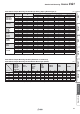
Bore size [mm]
20 25 32 40 50 63
Basic weight 0.14 0.23 0.35 0.57 1.04 1.49
Single knuckle joint 0.05 0.09 0.09 0.10 0.22 0.22
Double knuckle joint (with pin) 0.05 0.09 0.09 0.13 0.26 0.26
Additional weight per 50 mm of stroke
0.05 0.07 0.09 0.15 0.22 0.26
Additional weight with air cushion 0.01 0.01 0.02 0.02 0.03 0.03
Weight reduction for female rod end −0.01 −0.02 −0.02 −0.05 −0.10 −0.10
Symbol Specifi cations
-XC6
Made of stainless steel
-XC8
Adjustable stroke cylinder/Adjustable extension type
∗
-XC9
Adjustable stroke cylinder/Adjustable retraction type
∗
-XC13
Auto switch rail mounting
∗
-XC20
Head cover axial port
∗
-XC22
Fluororubber seal
∗
-XC85
Grease for food processing equipment
Mounting Basic
Standard Rod end nut
Option
Single knuckle joint
Double knuckle joint
∗
(with pin)
Bore size
[mm]
Standard stroke [mm]
∗
20
25, 50, 75, 100, 125, 150
25, 32
25, 50, 75, 100, 125, 150, 200
40, 50, 63
25, 50, 75, 100, 125, 150,
200, 250, 300
Bore size [mm]
20 25 32 40 50 63
Action Double acting, Single rod
Lubricant Not required (Non-lube)
Fluid Air
Proof pressure 1.5 MPa
Maximum operating pressure
1.0 MPa
Minimum operating pressure
0.05 MPa
Ambient and fl uid
temperature
Without auto switch: –10°C to 70°C
(No freezing)
With auto switch : –10°C to 60°C
Piston speed 50 to 1000 mm/s
Stroke length tolerance
Up to 300 st
+1.4
0
mm
Cushion Rubber bumper, Air cushion
Made to Order
(For details, refer to pages 49 to 65.)
Refer to pages 42 to 47 for cylinders with
auto switches.
· Auto switch proper mounting position
(detection at stroke end) and its mounting
height
· Minimum stroke for auto switch mounting
· Operating range
· Auto switch mounting brackets/Part no.
Specifi cations
Weights
Accessories Standard Strokes