
Datasheet


18
Z
Z
Number of
auto switches
∗ For applicable auto switches,
refer to the table below.
Auto switch
Made to Order
For details, refer to page 19.
If a built-in magnet cylinder without an auto switch is required,
there is no need to enter the symbol for the auto switch.
(Example) CDG1WFA32-100Z
Built-in Magnet Cylinder Model
Bore size
Type
With auto switch
(Built-in magnet)
Double acting,
double rod type
∗ Not available for ø80 or ø100.
∗ Mounting bracket is shipped together with the
product, but not assembled.
∗ The cylinder for F, L mounting types is Z: Basic
(without trunnion mounting female thread).
Mounting
Refer to “Standard Strokes” on page 19.
Note)
In the case of w/rod boot,
and a foot bracket or rod
fl ange as a bracket, those
parts are to be assembled
at the time of shipment.
∗ For female rod end, no rod
boot is provided.
Suffi x for cylinder (Rod boot)
Cylinder stroke [mm]
M9BW
With auto switch
100
100
CG1W
25N
N
L
25L
CDG1W
B
Basic
Z
∗
Basic (without trunnion mounting female thread)
L
Axial foot
F
Flange
U
∗
Trunnion
N
Rubber bumper
A
Air cushion
—
Without auto switch
—
2 pcs.
S
1 pc.
n
“n” pcs.
—
Without rod boot
One
end
J
Nylon tarpaulin
K
Heat resistant tarpaulin
Both
ends
JJ
Nylon tarpaulin
KK
Heat resistant tarpaulin
50
50 mm
63
63 mm
80
80 mm
100
100 mm
20
20 mm
25
25 mm
32
32 mm
40
40 mm
Rod end thread
—
Male rod end
F
Female rod end
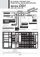
Series CG1W
ø20, ø25, ø32, ø40, ø50, ø63, ø80, ø100
Air Cylinder: Standard Type
Double Acting, Double Rod
How to Order
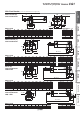
Applicable Auto Switches/Refer to the Auto Switch Guide for further information on auto switches.
Type
Special function
Electrical
entry
Indicator light
Wiring
(Output)
Load voltage Auto switch model Lead wire length
[m]
Pre-wired
connector
Applicable load
DC AC
Applicable bore size
0.5
(—)
1
[m]
3
(L)
5
(Z)
None
(N)
ø20 to ø63 ø80, ø100
Perpendicular
In-line In-line
Solid state auto switch
–––––
Grommet
Yes
3-wire
(NPN)
24 V
5 V,12 V
—
M9NV M9N
—
—
IC
circuit
Relay,
PLC
——
G59
—
—
3-wire
(PNP)
M9PV M9P
—
—
——
G5P
—
—
2-wire 12 V
M9BV M9B
—
—
—
——
K59
—
Connector
—
H7C
—
—
—
Diagnostic
indication
(2-colour indication)
Grommet
3-wire
(NPN)
5 V,12 V
M9NWV M9NW
—
—
IC
circuit
——
G59W
—
—
3-wire
(PNP)
M9PWV M9PW
—
—
——
G5PW
—
—
2-wire 12 V
M9BWV M9BW
—
—
—
——
K59W
—
—
Water resistant
(2-colour indication)
3-wire (NPN)
5 V,12 V
M9NAV
∗∗
M9NA
∗∗
—
—
IC
circuit
3-wire (PNP)
M9PAV
∗∗
M9PA
∗∗
—
—
2-wire 12 V
M9BAV
∗∗
M9BA
∗∗
—
—
—
——
G5BA
∗∗
——
—
Diagnostic output (2-colour indication)
4-wire (NPN) 5 V,12 V
—
H7NF
—
—
—
IC circuit
Reed auto switch
–––––
Grommet
Yes
3-wire (Equiv. to NPN)
—
5 V
—
A96V A96
—
—
—— —
IC circuit
—
2-wire 24 V
12 V
100 V
A93V A93
—
—
——
—
Relay,
PLC
None
100 V or less
A90V A90
—
—
—— —
IC circuit
Yes
100 V, 200 V
—
B54
—
——
—
None
200 V or less
—
B64
—
—— —
Connector
Yes
——
C73C
—
—
—
None
24 V or less
—
C80C
—
—
—
IC circuit
Diagnostic indication (2-colour indication)
Grommet
Yes
—— —
B59W
—
—— —
—
∗ Since there are other applicable auto switches than listed, refer to page 47 for details.
∗ For details about auto switches with pre-wired connector, refer to the Auto Switch Guide.
∗ The D-A9쏔쏔/M9쏔쏔쏔 auto switches are shipped together, (but not assembled). (However, only the auto switch mounting brackets are assembled before shipment.)
∗∗∗
Water resistant type auto switches can be mounted on the above models, but in such case SMC cannot guarantee the water resistance.
A water-resistant type cylinder is recommended for use in an environment which requires water resistance. However, please contact SMC for water-resistant products of ø20 and ø25.
∗ Solid state auto switches marked with “쑗” are produced upon receipt of order.
∗ Lead wire length symbols: 0.5 m·················· — (Example) M9NW
1 m·················· M
(Example) M9NWM
3 m··················
L
(Example) M9NWL
5 m··················
Z
(Example) M9NWZ
None
···············
N
(Example) H7CN
CG1CG1WCG1CG1KCG1KWCG1R
StandardNon-rotating RodDirect Mount
Double Acting, Single RodDouble Acting, Double Rod
Single Acting, Spring Return/Extend
Double Acting, Single RodDouble Acting, Double RodDouble Acting, Single Rod
Auto SwitchMade to Order