
Datasheet


41
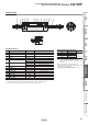
Series CG1R
GA
X
øD
GB
F
øI
WD
Wθ
°
10
°
GB
F
øI
Width across
flats
KA
Width across
flats
KA
øE
0
−0.05
H1
H1
øE
0
−0.05
R0.4
LH
L
LX
L
2 x øLD
L
LH
LX
L
2 x øLD
WC
ZZ
+ Stroke
S + StrokeH
A
AL Y
N
K
X
GA
WA
WB
Width across
flats
B1
MM
Width across
flats
B1
ZZ + Stroke
S + StrokeH
A
AL Y
N
NA
MM
2 x RcP
2 x P
K
MM
Effective depth A1
H
ZZ
+ Stroke
port location
Cushion valve,
Width across flats
WH
R0.4
øD
[mm]
Female Rod End
[mm]
With Air Cushion
[mm]
Female rod end
ø20, ø25
With rubber bumper
With air cushion
Bore size
Stroke
range
AALB1 DEFGAGBHH1 I K KA L LD LH LX MM N P S X Y ZZ
20
Up to 150
18 15.5 13 8 12 2 20 10 27 5 26 5 6 30.4
ø5.5, ø9.5 depth of counterbore 6
15 18
M8 x 1.25
27 1/8 75 38 11 104
25
Up to 200
22 19.5 17 10 14 2 22 10 32 6 31 5.5 8 36.4
ø6.6, ø11 depth of counterbore 7
18 22
M10 x 1.25
29 1/8 77 44 12 111
32
Up to 200
22 19.5 17 12 18 2 26 10 32 6 38 5.5 10 42.4
ø9, ø14 depth of counterbore 9
21 24
M10 x 1.25
33 1/8 83 45 13 117
40
Up to 300
30 27 19 16 25 2 30 10 39 8 47 6 14 52.4
ø11, ø17.5 depth of counterbore 12
26 32
M14 x 1.5
37 1/8 94 55 16 135
50
Up to 300
35 32 27 20 30 2 33 12 45 11 58 7 18 64.5
ø14, ø20 depth of counterbore 14
32 41
M18 x 1.5
44 1/4 108 62 17 155
63
Up to 300
35 32 27 20 32 2 39 12 45 11 72 7 18 76.6
ø18, ø26 depth of counterbore 18
38 46
M18 x 1.5
50 1/4 114 64 19 161
Bore size
Stroke
range
P WAWBWCWDWθ WH
20
Up to 150 M5 x 0.8 22 15 5.5 2 25° 1.5
25
Up to 200 M5 x 0.8 24 14.5 7 2 25° 1.5
32
Up to 200 Rc1/8 28 14 11.5 — 25° 1.5
40
Up to 300 Rc1/8 32 15 15 — 20° 1.5
50
Up to 300 Rc1/4 36 16 17.5 — 20° 3
63
Up to 300 Rc1/4 42 17 20.5 — 20° 3
Bore size
A1 HMMZZ
20
8 13 M4 x 0.7 90
25
8 14 M5 x 0.8 93
32
12 14 M6 x 1 99
40
13 15 M8 x 1.25 111
50
18 16 M10 x 1.5 126
63
18 16 M10 x 1.5 132
Basic with Bottom Mounting