
Datasheet


12
467
0.6
1.5 1.5
0.4
0.5
0.3
0.2
0.15
0.1
0.05
0.04
0.03
0.02
0.015
0.01
0.2
0.3
0.4
0.8
0.6
0.5
0.7
Subject to change
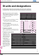
SI UNITS, SYMBOLS AND DIMENSIONING
Average
air consumption
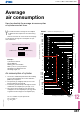
How to calculate the average air consumption
of cylinders and air lines.
Y
ou need to know the average air consumption
to determine the compressor size and running
cost.
Here we show how to use the charts on this page
to calculate the average air consumption of cylin-
ders and air lines.
Example:
Cylinder bore: 50 mm
Stroke: 600 mm
Working pressure: 0.5 MPa
Work cycles: 5 cycles per minute
Air tubing inner diameter: 6 mm
Air tubing length: 2 m
Air consumption of cylinder
1. Use chart 1 and nd the point where the working
pressure line (0.5 MPa) crosses the stroke line
(600 mm). See point A.
2. From point A, go straight up until you cross the
bore line (50 mm). See point B.
3. From there, go horizontally to the right or the left
and nd air consumption per cycle (Q
t
) = 13 l
n
.
4. Since there are ve working cycles per minute,
multiply the air consumption per cycle (Q
t
) with 5
to get the actual average air consumption (Q
v
).
Q
v
= Q
t
number of cycles per minute
Q
v
= 13 l
n
/min 5
Q
v
= 65 l
n
/min
Chart 1 – cylinder air consumption per cycle
Single stroke (extension or retraction)
Working pressure (MPa)
Stroke (mm) Air consumption per cycle (l
n
)
Air consumption per cycle (l
n
)
Cylinder bore (mm)
Double stroke = cycle (extension and retraction)
1 500
2 000 2 000
1 000
500
400
300
200
150
100
50
40
30
20
15
10
5
4
3
2
1
1 500
1 000
500
400
300
200
150
100
50
40
30
20
15
10
5
4
3
2
1
5 000
4 000
3 000
2 000
1 500
1 000
50
100
150
200
300
400
500
160
125
100
80
63
50
40
32
25
20
16
10
6
160
125
100
80
63
50
40
32
25
20
16
10
6
160
125
100
80
63
50
40
32
25
20
16
10
6
160
125
100
80
63
50
40
32
25
20
16
10
6
A
B