
Specifications


3.2.6 Logic Voltage Output
If the AFS-3 will be connected to an external sensing device, there are jumpers inside the AFS-3 that can be set so
that the output relay switches a logic voltage to indicate an alert condition.
Jumper positions JP2-4 set the logic voltage output. No jumpers are installed at these positions at the factory and
the relay contacts are dry--no voltage. JP4 places +5VDC (current limited throuh a 2.2K pull up resistor) on the
common (C) relay contact. JP2 and JP3 ground the normally closed (NC) and normally open (NO) relay contacts
respectively.
To generate a logic high (+5VDC) in the alert condition, place a jumper on JP2 so that the logic voltage normally
bleeds off through the internal resistor to ground through the NC contact. When the relay is energized during the alert
condition the contact to ground will be broken and the logic voltage will rise to +5VDC. Reverse the logic by placing a
jumper at JP3 instead of JP2.
3.2.7 Audible Alert Enable/Disable
Enable the audible alert inside the AFS-3 by placing a jumper at position JP1. Disable the audible alert by removing
the jumper at position JP1. The audible alert is enabled by default.
The audible alert can be constant or pulsing. Place a jumper at position JP5 to make the alert sound constant.
Remove the jumper at position JP5 to make the alert sound pulse. The alert pulses by default.
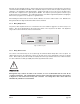
Figure 3.2; AFS-3 internal jumper locations
3.2.8 Audio/Silence Detector
Normally the AFS-3 senses loss of audio. When all audio is lost for the delay period the failsafe triggers the alert
condition. The system can be set to sense audio presence instead of silence by placing a jumper at position JP6. In
this “reverse” mode the failsafe triggers an alert when audio (rather than silence) is present for the delay period.
AFS-3 Installation page 3.3