
User's Manual

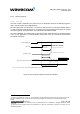


Table Of Contents
- General description
- Interfaces
- General Purpose Connector (GPC)
- Power supply
- Electrical information for digital I/O
- LCD interface
- SPI Auxiliary bus
- Keyboard interface
- Main serial link (UART1)
- Auxiliary serial link (UART2)
- SIM interface
- General Purpose Input/Output
- Activity status indication
- Analog to Digital Converter (ADC)
- Audio interface
- Battery charging interface
- ON / ~OFF
- BOOT (optional)
- Reset signal (~RST)
- External Interrupt (~INTR)
- VCC output
- Real Time Clock Supply (VCC_RTC)
- RF interface
- Technical specifications
- Appendix

WM_PRJ_Q2400_PTS_002 - 003
14th April 2003
2.17.2 Reset sequence
To activate the « emergency » reset sequence, the ~RST signal has to be set to low for 500 µs
minimum.
As soon as the reset is complete, the AT interface answers « OK » to the application. For this, the
application has to send AT↵. If the application manages hardware flow control, the AT command
can be sent during the initialisation phase. Another solution is to use the AT+WIND command to get
an unsollicited status from the module.
For further details, refer to AT commands documentation [3].
RESET m ode
I
BB+ RF
=20
to 40 mA
EXTERN A L RST
ST A T E OF T H E M OD U LE
Module READY
M in:500
µ
s
Typ:2 m s
A
T answ ers “ OK”
Module READY
SIM and netw ork dependent
Module ON
I
BB+ RF
<120 mA
w ithout loc update
Figure 5: Reset sequence diagram
2.18 External Interrupt (~INTR)
The WISMO module provides an external interrupt input ~INTR. This input is very sensitive and an
interrupt is activated on high to low edge. If this signal is not used it can be left open. If used this
input has to be driven by an open collector or an open drain output.
This input is used for instance to power OFF automatically the module.
Pin description
Signal Pin number I/O I/O type Description
~INTR
16 I CMOS External Interrupt
Electrical characteristics
Parameter Min Max Unit
V
IL
-0.5 0.7 Volt
V
IH
2.2 3.0 Volt
confidential ©
Page : 36 / 63
This document is the sole and exclusive property of WAVECOM. Not to be distributed or divulged without prior written
agreement.
Ce document est la propriété exclusive de WAVECOM. Il ne peut être communiqué ou divulgué à des tiers sans son
autorisation préalable.