SINAMICS G150 NEMA Enclosed Drives SINAMICS Drives Catalog D 11.7 Part 1 2013 Answers for industry.
The Engineering Manual Related Catalogs SINAMICS G130 D11 • 2011 Drive Converter Chassis Units SINAMICS G150 Drive Converter Cabinet Units (IEC) SINAMICS G130 Drive Converter Chassis Units SINAMICS G150 Drive Converter Cabinet Units Engineering Manual for SINAMICS G130 Drive Chassis, SINAMICS G150 Enclosed Drives, SINAMICS S120 Drive Chassis, SINAMICS S120 Cabinet Modules, SINAMICS S150 Enclosed Drives E86050-K5511-A101-A5-7600 DRCA-D1100-0412 SINAMICS Drives Answers for industry.
SINAMICS Drives SINAMICS G150 NEMA enclosed drives SINAMICS G150 NEMA enclosed chassis Catalog D11.7 (Part 1) – 2013 Introduction 1 SINAMICS G150 NEMA Type A enclosed drives 2 SINAMICS G150 NEMA Type C enclosed chassis 3 Engineering information 4 Quality The products and systems described in this catalog are produced/ distributed in accordance with the requirements of a quality management system which has been certified to ISO 9001:2008.
SINAMICS G150 NEMA 1 Introduction The SINAMICS drives family One Family, One Source, All Applications Application SINAMICS is the family of drives from Siemens designed for industrial applications that offers solutions for all drive tasks: Basic pump and fan applications in the process industry.
1 SINAMICS G150 NEMA 5 Introduction 1/2 The members of the SINAMICS drives family SINAMICS low voltage drives SINAMICS DC drives SINAMICS medium voltage drives SINAMICS G150 Siemens D11.
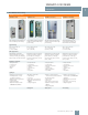
SINAMICS G150 NEMA 1 Introduction The SINAMICS drives family SINAMICS low voltage drives SINAMICS G110 SINAMICS G120 SINAMICS G110D SINAMICS G120D The versatile single motor drive for low power ratings The modular single motor drive for low up to medium power ratings The distributed single motor drive for basic solutions The distributed single motor drive for high performance 380 to 690 V 3 ph. AC 0.15 to 400 HP (0.37 to 250 kW) 380 to 480 V 3 ph. AC 1 to 10 HP (0.75 to 7.5 kW) 380 to 480 V 3 ph.
SINAMICS G150 NEMA Introduction 1 The SINAMICS drives family SINAMICS low voltage drives SINAMICS G120E SINAMICS G130 SINAMICS G150 (IEC) SINAMICS G150 NEMA The versatile enclosed drive for low to medium power ratings The modular single motor drive solution for drives with a high power rating The universal enclosed drive solution for drives with a high power rating The universal high power enclosed drive solution per North American standards 380 to 690 V 3 ph.
SINAMICS G150 NEMA 1 Introduction The SINAMICS drives family SINAMICS low voltage drives SINAMICS DC drives SINAMICS medium voltage drives SINAMICS S120 SINAMICS S150 SINAMICS DCM SINAMICS GM150 / SM150 SINAMICS GL150 / SL150 The flexible, modular applied drive system for demanding drive tasks The drive solution for demanding high power single motor drives The scalable drive system for basic and demanding applications Drive solutions for single motor and multi motor medium voltage drives 380 to
SINAMICS G150 NEMA Introduction 1 Application of SINAMICS G150 SINAMICS G150 is an enclosed variable speed drive ideal for all applications that involve moving, conveying, pumping or compressing solids, liquids or gases. This includes both variable torque applications such as pumps, fans, blowers, and compressors, as well as constant torque applications that do not require regeneration such as mixers, extruders and mills.
SINAMICS G150 NEMA 1 Introduction SINAMICS G150 – A Global Product SINAMICS G150 is a global product. However, regional differences in regulations, standards, specifications and voltage levels for power and control require modifications to the packaging (enclosure) and auxiliary components. SINAMICS G150 enclosed drives are therefore offered in versions designed to IEC (European) as well as to NEMA (North American) standards. SINAMICS G150 designs to NEMA vs.
2 SINAMICS G150 NEMA Type A enclosed drive5 2/2 Product design 2/3 Selection and ordering data HP and current ratings 2/4 Technical data Noise level Heat loss Weights Dimensions 2/5 Outline dimension sketch 2/6 Options Table of standard option codes 2/7 Options combination matrix Valid and invalid combinations of options 2/8 Description of options Detailed description of each standard option 2/14 Custom options Siemens D11.
SINAMICS G150 NEMA Type A enclosed drive Product design SINAMICS G150 NEMA type A enclosed drive is ready to install and run, complete with all necessary accessories. It is offered with a large variety of standard and custom input and output options, such as different enclosure types, input contactor, across the line or solid state bypass circuits, output reactor and a range of control options.
SINAMICS G150 NEMA Type A enclosed drive Selection and ordering data Note: HP ratings are provided as a guide only, for standard 2, 4 or 6 pole motors. Actual motor currents may be higher, especially for motors with 8 or more poles. Select a drive based on motor FLA (full load amps) and overloads. Refer also to engineering information.
SINAMICS G150 NEMA Type A enclosed drive Technical data SINAMICS G150 NEMA Type A enclosed drive Output (light overload) at 460 V or 575 V, 60 Hz Noise level LpA (1m) 50/60 Hz Cooling air flow demand Heat loss Short circuit current rating (SCCR) Weight approx. (std enclosure w/o options) Model No. HP dB(A) cfm kW kA lb kg Supply voltage 380 V to 480 V 3 ph. AC 2 6SL3710-1GE32-1AU3 150 67 / 68 360 2.9 65 950 430 6SL3710-1GE32-6AU3 200 69 / 73 487 3.
SINAMICS G150 NEMA Type A enclosed drive Outline dimension sketch 10 ” / 2 5 0 mm S pa c ing to c e iling if re a r is m o un te d a ga ins t w a ll AIR OUT T o ph at Add-on Output Options Cabinet SINAMICS 79” / 2000 mm 94.5” / 2400 mm 2 AIR IN 4” / 100 mm O p tio n MM06 06 Option Option M07 8” / 200 mm 23.6” / 600 mm SIDE VIEW Wo WN FRONT VIEW Note: • The drawing shows the SINAMICS G150 type A enclosed drive with louvers (option M23, M43 or M54).
SINAMICS G150 NEMA Type A enclosed drive Options Option code 2 Description Comment Testing F03 Visual inspection by customer F71 Witnessed function test without motor F75 Witnessed function test with test-bay motor, no load F77 Witnessed test incl.
SINAMICS G150 NEMA Type A enclosed drive Options combination matrix The following tables provide an overview of possible and impermissible combinations of standard options. Please refer to the descriptions of options for more information. Custom configurations may be possible to provide combinations not available as standard – please contact the factory.
SINAMICS G150 NEMA Type A enclosed drive Description of options 2 Standard documentation Customer drawings supplied with the new SINAMICS G150 NEMA are always job specific (showing the configuration actually supplied, options not provided are not shown). F03, F71, F75, F77, F97 Witnessed (or observed) testing All customer documentation is provided in electronic format on a CD, which ships inside the drive. All documents are in pdf format (Adobe Acrobat) and are supplied in English and a copy in Spanish.
SINAMICS G150 NEMA Type A enclosed drive Description of options G20 CBC10 communication board CANopen The CBC10 Communication Board is used to interface the CU320-2 Control Unit of the SINAMICS G150 to the CAN (Controller Area Network) protocol.
SINAMICS G150 NEMA Type A enclosed drive Description of options K50 SMC30 sensor module for speed feedback The SMC30 encoder module is used to connect a speed feedback encoder to the drive. Rotary pulse encoder signals are converted for evaluation via the DRIVE-CLiQ interface of the controller. 2 The following encoders are supported by the SMC30: • TTL encoders • HTL encoders The motor temperature can also be detected using a KTY84-130 sensor or PTC thermistors.
SINAMICS G150 NEMA Type A enclosed drive Description of options The dV/dt filter plus VPL consists of two components: the dV/dt reactor and the VPL (Voltage Peak Limiter), which limits voltage peaks and returns the energy to the DC link. It is housed in an add-on options cabinet. Option L10 cannot be combined with option M78 (Motor side top cable exit).
SINAMICS G150 NEMA Type A enclosed drive Description of options P20 : Permitted output for a period of 20 s, cycle time 90 s If higher braking powers are required, please consult factory. For drives with multiple power blocks, multiple braking units and resistors may be connected. Refer to engineering information for further information. 2 L87 Insulation Monitor for ungrounded supplies An insulation monitor must be used if the drive is operated on an ungrounded power supply.
SINAMICS G150 NEMA Type A enclosed drive Description of options M90 Lifting beam/eye bolts Note: Option M90 is strongly recommended, to enable lifting the drives off their pallet safely. push button is mounted on the door. When delivered, the button circuit is preset to 120 V AC. Jumpers must be set when using 24 V DC. For single cabinets up to a width of 24” (600 mm), eye bolts are provided. For larger enclosures transportation beams are provided.
SINAMICS G150 NEMA Type A enclosed drive Description of options T58 Nameplate English/French The standard nameplate text is in both English and Spanish. This option provides for a nameplate with both English and French text. 2 U90 UL listing per UL508A The drive is provided with the UL listing mark per UL508A (UL file number E83449). UL listing mark The basis for UL listing is the maximum continuous output current rating of the drive.
3 SINAMICS G150 NEMA Type C enclosed chassis 5 3/2 Product design 3/3 Selection and ordering data HP and current ratings 3/4 Technical data Noise level Heat loss Weights Dimensions 3/5 Outline dimension sketch 3/6 Options Table of standard option codes 3/7 Options combination matrix Valid and invalid combinations of options 3/8 Description of options Detailed description of each standard option 3/11 Line side components for SINAMICS G150 NEMA type C enclosed chassis Circuit breaker Semicond
SINAMICS G150 NEMA Type C enclosed chassis Product design SINAMICS G150 NEMA type C enclosed chassis is a drive in a very compact enclosure, for use with external disconnect and circuit protection (for example in an existing MCC). It is offered with a limited range of standard options, such as enclosure type, input line reactor or speed encoder feedback module.
SINAMICS G150 NEMA Type C enclosed chassis Selection and ordering data Light overload High overload Output at 460 V or 575 V, 60 Hz Output at 460 V or 500 V 50 Hz Base load current IL 2) 4) Output at 460 V or 575V 60Hz Output at 400 V or 500 V, 50 Hz Base load current IH3) 4) Rated Rated SINAMICS G150 output input NEMA Type C current current 5) Enclosed chassis IN 1) 4) HP kW A HP kW A A A Order No. Supply voltage 380 V to 480 V 3 ph.
SINAMICS G150 NEMA Type C enclosed chassis Technical data SINAMICS G150 NEMA Type C enclosed chassis Output (light overload) at 460 V or 575 V, 60 Hz Noise level LpA (1m) 50/60 Hz, Cooling air flow demand Heat loss Short circuit current rating (SCCR) Weight approx. (std enclosure w/o options) Model No. HP dB(A) cfm kW kA lb kg Supply voltage 380 V to 480 V 3 ph. AC 6SL3710-1GE32-1CU3 150 67 / 68 360 2.9 65 480 220 6LS3710-1GE32-6CU3 200 69 / 73 487 3.
SINAMICS G150 NEMA Type C enclosed chassis Technical data Spacing to ceiling if rear is mo un ted against wall 10 ” / 250 mm AIR OUT SINAMICS 79” / 2000 mm 94.5” / 2400 mm Tophat 3 AIR IN 4” / 100 mm Option M06 Option M07 8” / 200 mm 23.6” / 600 mm WN SIDE VIEW FRONT VIEW Note: • The drawing shows the SINAMICS G150 type C enclosed chassis with louvers (option M23, M43 or M54). • For transport reasons, the tophats are delivered separately and must be fitted on site.
SINAMICS G150 NEMA Type C enclosed chassis Options 3 Option code Description Comment Enclosure Options M06 M07 M23 M43 M54 M90 Y09 Power Options Base (plinth) 4” (100 mm) Base (plinth) 8” (200 mm) Enclosure NEMA 1 filtered Enclosure IP43 Enclosure NEMA 12 (ventilated) Lifting beam/eye bolts Special enclosure paint color (specify color) Requires current derate (refer to page 4/3) Recommended: Required to lift the drive off pallet Please specify required color in text L23 Input line reactor Miscellane
SINAMICS G150 NEMA Type C enclosed chassis Options combination matrix The following tables provide an overview of which standard options can be combined with each other, and which cannot. Please refer to the descriptions of options for more information. Custom configurations may be possible to provide combinations not available as standard – please contact the factory.
SINAMICS G150 NEMA Type C enclosed chassis Description of options Standard documentation Customer drawings supplied with the new SINAMICS G150 NEMA are always job specific (showing the configuration actually supplied, options not provided are not shown). F03, F71, F75, F77, F97 Witnessed (or observed) testing All customer documentation is provided in electronic format on a CD, which ships inside the drive. All documents are in pdf format (Adobe Acrobat) and are supplied in English and a copy in Spanish.
SINAMICS G150 NEMA Type C enclosed chassis Description of options G20 CBC10 communication board CANopen The CBC10 Communication Board is used to interface the CU320-2 Control Unit of the SINAMICS G150 to the CAN (Controller Area Network) protocol.
SINAMICS G150 NEMA Type C enclosed chassis Description of options M07 Base (plinth) 8” (200 mm) high The 8” enclosure base provides more space for bending and routing cables. The base is delivered already mounted to the enclosure. The height of the operator panel changes accordingly. U90 UL listing per UL508A The drive is provided with the UL listing mark per UL508A (UL file number E83449). The base color is the same as the enclosure, RAL 7035 (light grey).
SINAMICS G150 NEMA Type C enclosed chassis Line side components for SINAMICS G150 NEMA type C enclosed chassis SINAMICS G10 NEMA type C enclosed chassis do not include any line side components (except for the optional line reactor) – these components need to be added externally, for example in an MCC.
SINAMICS G150 NEMA Type C enclosed chassis Line side components for SINAMICS G150 NEMA type C enclosed chassis Input line reactor A minimum 2% input line reactor is recommended for most installations. It can be included in the enclosure of the enclosed chassis (option L23) or alternatively be mounted externally, for example in an MCC with the other line side components. The recommended type of input line reactor is listed below.
4 SINAMICS G150 NEMA Engineering information5 1 4/2 Technical data Electrical and mechanical data Compliance with standards Ambient conditions Mechanical stability 4/3 Derating data Current derating due to altitude and temperature Voltage derating due to altitude Current derating due to pulse frequency 4/5 Motor and drive sizing, overloads Dimensioning of drives Motor and drive sizing Overload capability 4/6 Input and output reactors and filters, harmonics, motor design Input line reactor Harmonic
SINAMICS G150 NEMA Engineering information Technical data Electrical data Supply voltages and output ranges Supply systems Line frequency Output frequency Power factor fundamental / total Converter efficiency Control method Fixed speeds Skipped frequency ranges Setpoint resolution Braking operation Mechanical data Type of enclosure Enclosure details Enclosure color Type of cooling Noise level LpA (1 m) Environmental protection Compliance with standards Standards UL listing CE marking EMC conformanc
SINAMICS G150 NEMA Engineering information Derating data Current derating as a function of the installation altitude and ambient temperature If SINAMICS G150 drives are operated at an installation altitude >6,600 ft (2,000 m) above sea level, the maximum permissible output current can be calculated using the following tables. Note that the enclosure type selected for the drive must also be taken into account.
SINAMICS G150 NEMA Engineering information Derating data Current derating as a function of the pulse frequency If the drive is set to operate at increased pulse frequencies, the output current values listed in the technical specifications must be derated in accordance with the tables below.
SINAMICS G150 NEMA Engineering information Motor and drive sizing, overloads Dimensioning of drives The SINAMICS G150 drive may be operated with both variable torque and constant torque loads at either low or high overload duties. For variable torque (VT) loads (torque is proportional to the square of the speed) such as fans/blowers, centrifugal pumps and compressors, the rated continuous output current of the drive should be at least equal to the motor current at full torque at the required load point.
SINAMICS G150 NEMA Engineering information Input and output reactors and filters, harmonics, motor design A 2% or 3% inductor primarily assures the minimum current form factor, and improves the sensitivity of the VFD to voltage spikes. A minimum 2% input line reactor is recommended unless the drive is powered via a separate drive isolation transformer, or if the ratio between the line short circuit capacity at the point of connection and the rated drive output is low (i.e.
SINAMICS G150 NEMA Engineering information Operator panel AOP30 advanced operator panel This information can be found on the motor nameplate, and is entered into the screens on the display by following a short, menu-driven procedure. The type of motor cooling must be entered in addition. Motor data Back p0304 MOT.U_rated p0305 MOT. I_rated p0307 MOT.P_rated p0308 MOT.CosPhi_ rated Help Change G_D011_en_00048 400.0 V 405.0 A 235.0 kW 0.
SINAMICS G150 NEMA Engineering information Control interfaces, Firmware functions Control interfaces Both a PROFIBUS interface on the CU320-2 DP control unit and a terminal module are provided as standard for use as the control interface. The terminal module permits connection to the higher level control using analog and digital signals. Optionally the analog and digital inputs and outputs can be expanded by a second terminal module. Additional digital I/O on the CU320-2 control unit may be utilized too.
SINAMICS G150 NEMA Engineering information CU320-2 Control Unit The communication, open-loop and closed-loop control functions for the SINAMICS G150 drive are executed in the CU320-2 Control Unit.
SINAMICS G150 NEMA Engineering information CBE20 Communication Board Ethernet EtherNet/IP EtherNet/IP (EtherNet Industrial Protocol) is an open standard predominantly used in the automation industry. EtherNet/IP is supported by the Open DeviceNet Vendor Association (ODVA).
SINAMICS G150 NEMA Engineering information Digital and analog inputs and outputs TM31 Terminal Module TM31 specifications Digital inputs • Voltage • Low level (an open digital input is interpreted as “low”) • High level • Current consumption (at 24 V DC) • Signal propagation delays for digital inputs -3 V + 30 V -3 V to +5 V 15 V to 30 V Typ. 10 mA L to H: approx. 50 µs H to L: approx. 100 µs • Max. wire size #16 AWG (1.5 mm2) Digital outputs (continuously short-circuit-proof) 24 V DC • Voltage • Max.
SINAMICS G150 NEMA Engineering information RTD monitor TM150 Terminal Module (options G51 and G52) The TM150 RTD module is suitable for monitoring a variety of temperature sensors, over the temperature range -146°F (-99°C) to +480°F (+250°C): • Pt100 - Platinum RTD 100 ohm • Pt1000 - Platinum RTD 1,000 ohm • KTY84 - temperature sensor • PTC - Positive temperature coefficient thermistor • Temperature switch (NC) contact (for example Thermoclick or bimetallic switch) 4 Up to 12 sensors in 2-wire connection
SINAMICS G150 NEMA Engineering information Interface for speed feedback encoder SMC30 Sensor Module (options K50 and K52) When is a speed feedback encoder recommended? SINAMICS G150 is capable of accurately controlling torque at and near zero speed without a speed feedback encoder. It can do so during motoring operation, i.e. for applications without an overhauling load that applies torque to the motor. A speed feedback encoder is therefore required only rarely.
SINAMICS G150 NEMA Engineering information Safety integrated Safety Integrated functions The integrated safety functions of SINAMICS provide highly effective application-oriented protection for personnel and machinery. The Safety Integrated functions are implemented electronically and therefore offer short response times in comparison to solutions with externally implemented monitoring functions.
SINAMICS G150 NEMA Engineering information Safety integrated Safety Basic Functions and Safety Extended Functions The Safety Integrated functions of the SINAMICS drive system are subdivided into what are known as Safety Basic Functions and Safety Extended Functions (terminology according to IEC 61800-5-2): • Basic Functions - Safe Torque Off (STO) - Safe Stop 1 (SS1, time-controlled) - Safe Brake Control (SBC) The Safety Basic functions are included in the standard scope of delivery of the drive firmware an
SINAMICS G150 NEMA Engineering information Safety integrated Safe Brake Control (SBC) Function description The Safe Brake Control SBC is used to control holding brakes, which are active in the no-current state, e.g. motor holding brakes (actuated using spring force). The brake is controlled through two channels in a safety-relevant fashion.
SINAMICS G150 NEMA Engineering information Safety integrated Safety integrated Safely-Limited Speed (SLS, with encoders) Safe Direction (SDI, with encoders) Function description Using the Safely-Limited Speed function, the drive is monitored against a parameterizable maximum velocity. Four different limit values can be activated. Just the same as for SOS, the speed setpoint is not independently influenced.
SINAMICS G150 NEMA Engineering information 4/14 Safety integrated An overview of the SINAMICS Safety Integrated functions plus their boundary conditions is provided in the following table.
SINAMICS G150 NEMA Engineering information Safety integrated The principle of operation of Safety Integrated Two independent shutdown paths There are two shutdown paths that are independent of one another. All shutdown paths are low active. This therefore ensures that when a component fails or there is a wire break, then the system always goes into the safe state.
SINAMICS G150 NEMA Engineering information Fail-safe inputs and outputs TM54F Terminal Module The TM54F Terminal Module (option K87) is a dual-processor I/O interface with 4 fail-safe digital outputs and 10 fail-safe digital inputs for using Safety Integrated functions of the SINAMICS G150 drive via external actuators and sensors. All of the available safety functions integrated in the drive can be controlled via the fail-safe digital inputs of the TM54F Terminal Module.
SINAMICS G150 NEMA Engineering information Technical data TM54F Terminal Module TM54F Terminal Module Current demand (X524 at 24 V DC) without DRIVE-CLiQ supply 0.2 A Scanning cycle tSI for fail-safe digital inputs or fail-safe digital outputs 4 ... 25 ms (adjustable) Max. current demand ext.
SINAMICS G150 NEMA Engineering information Safe Brake Adapter Safe Brake Adapter Option K88 Supply voltage of the motor holding brake 230 V AC Max. permissible current consumption of the • Motor holding brake 2A • Fast de-energization 2A Max, permissable cable lengths • to the brake 990 ft (300 m) Max. wire size #12 AWG (2.5 mm2) Safety Integrated Safety Integrity Level 2 (SIL2) acc. to IEC 61508, Performance Level d (PLd) acc. to ISO 13849-1 and Control Category 3 acc.
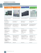
SINAMICS G150 NEMA Engineering information Braking units Two sizes of braking units are available for the SINAMICS G150 type A enclosed drive with braking powers of 100 kW (for 150 HP & 200 HP, 460V) and 200 kW (for larger 460 V and 575V units). For higher braking powers, braking units may be connected in parallel for larger drives (on request, not for all ratings). A thermal contact, which can be integrated into the drive’s alarm and shutdown sequence, is installed in the braking resistor for monitoring.
SINAMICS G150 NEMA Engineering information Braking units, maintenance accessory Example The design of the braking unit is to be calculated for a 200HP (132 kW) drive. Frame for exchanging power blocks The mean braking power is calculated as follows: The Mean braking power = 90 kW x 17 s / 90 s = 17.0 kW Peak power = 0.8 x 90 kW = 72.0 kW Power modules of SINAMICS G150 (and other SINAMICS and the MICROMASTER 4 chassis) contain one or more power blocks, depending on the frame size.
SINAMICS G150 NEMA Engineering information STARTER commissioning tool In addition, the following functions are available for optimization purposes: • Self-optimization of the controller settings (depending on the drive unit) • Trace to precisely record the signals • Numerous measuring functions such as step functions and frequency response analysis Diagnostics functions provide information about: • Control/status words • Parameter status • Conditions of use • Communication states The user-friendly STARTER
SINAMICS G150 NEMA Engineering information Drive Control Chart (DCC) Drive Control Chart (DCC) expands the scope of device functions by means of freely available closed-loop control, calculation and logic modules and offers a means by which technological functions can be graphically configured in the SINAMICS G150 drive system. DCC is installed as an additional application to the STARTER commissioning tool. allow the program behavior to be verified and, in the case of a fault, the cause identified.
SINAMICS G150 NEMA Service and support Engineering information Complete life cycle service For machine constructors, solution providers and plant operators: The service offering from Siemens industry, Automation and Drive Technologies includes comprehensive services for a wide range of different users in all sectors of the manufacturing and process industry. Our Service & Support accompanies you worldwide in all matters concerning automation and drives from Siemens.
Siemens Industry, Inc. 3333 Old Milton Parkway Alpharetta, GA 30005 1-800-241-4453 info.us@siemens.com www.usa.siemens.com/drives Subject to change without prior notice. Order No: DRCA-D1171-0313 All rights reserved. Printed in USA. ©2013 Siemens Industry, Inc. The information provided in this brochure contains merely general descriptions or characteristics of performance which in case of actual use do not always apply as described or which may change as a result of further development of the products.