
Operating Instructions


SED2 VFD Electronic Bypass Option Operating Instructions
6 Siemens Building Technologies, Inc.
Contactors
The Controller board provides two or three relay contact circuits controlled by the
Electronic Bypass Option: bypass, input, and output contactors. Each circuit includes
a NO relay. Controller board connector J7 enables circuit connections. The relay
circuits route power to the SED2 and the motor via the contactors. Controlling the
contactors through the relay circuits is the main function of the Controller board.
Bypass Contactor – The bypass relay on the Controller board controls the bypass
contactor. The output and bypass relays are interconnected to 120 Vac Hot. This
enables a safety circuit that prevents the bypass and output contactors from
simultaneously being energized.
Output Contactor – The output relay on the Controller board controls the output
contactor.
Input Contactor – The input relay on the Controller board controls the optional input
contactor.
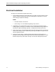
Keypad Functions
Bypass
STOP
RESET
Enable
Input
Contactor
Output
Contactor
Bypass
Contactor
Overload
Relay
VFD
Hand
Start
Remote
Start
INTERLOCK START LOGIC
Enable Commanded Proofed
Auto Bypass Enabled
Essential Services
VFD Fault
Safety Fault
Overload Fault
Motor
VFD0096R1
2-CONTACTOR KEYPAD
VFD Bypass
STOP
RESET
Input
On/Off
Enable
Input
Contactor
Output
Contactor
Bypass
Contactor
Overload
Relay
VFD
Hand
Start
Remote
Start
INTERLOCK START LOGIC
Enable Commanded Proofed
Auto Bypass Enabled
Essential Services
VFD Fault
Safety Fault
Overload Fault
Motor
VFD0097R1
3-CONTACTOR KEYPAD
Figure 4. E-Bypass Keypad Indicators and Pushbuttons.
The keypad provides user interface indicators and pushbuttons. The following table
describes specific pushbutton and indicator functions: