
User's Manual Part 2


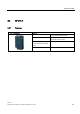

Table Of Contents
- 5 Readers
- 5.1 RF 310-R
- 5.1.1 Features
- 5.1.2 Indicators
- 5.1.3 Transmission window
- 5.1.4 Metal-free area
- 5.1.5 Minimum distance between several RF 310-R units
- 5.1.6 RF 310-R field data
- 5.1.7 Pin assignment of the IQ-Sense interface
- 5.1.8 Cable and connector pin assignment
- 5.1.9 Technical data of the RF 310-R
- 5.1.10 FCC information
- 5.1.11 RF 310-R ordering data
- 5.1.12 Dimension drawing
- 5.1 RF 310-R
- 6 Transponder/tags
- 7 Communication modules
- 8 Accessories
- A Appendix
- List of abbreviations
- Glossary
- Index

Transponder/tags
6.2 RF 340-T
RF 300
6-8 System Manual, 05/2005, (4)J31069 D0166-U001-A1-7618, --
6.2.2 Metal-free area
Direct mounting of the RF 340-T on metal is allowed.
Direct mounting of the RF 340-T on metal
0HWDO
Figure 6-3 Direct mounting of the RF 340-T on metal:
Flush-mounting of the RF 340-T in metal:
D
E
0HWDO
Figure 6-4 Flush-mounting of the RF 340-T in metal: