
Installation Instructions


Siemens Building Technologies / HVAC Products 74 319 0173 0 b G1637 14.02.2002 3/12
en
Installation Instructions
Place of installation
Choosing the place of installation
• In a dry room (in the case of room influence in the
reference room), e.g. in the living room, office, etc.
• Thermostatic radiator valves in the reference room
must be fully opened
• Mounting choices:
Wall mounting (inner wall, control panel front, etc.)
• Permissible ambient temperature: 0...35 °C
Electrical installation
• The local regulations for electrical installations
must be complied with
• The cables from the room unit to the controller and
the external sensor / switch carry low voltage
• Sensor cables may not be run parallel to mains
carrying cable
Permissible cable lengths
• To the controller:
Copper cable 0.25 mm
2
max. 25 m
Copper cable from 0.5 mm
2
max. 50 m
• To the extenal switch or sensor:
Copper cable 0.6 mm dia. max. 20 m
Copper cable from 1.0 mm
2
max. 50 m
Mounting and wiring the base
Mounting: Refer to the packaging
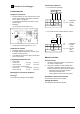
Wiring:
• With external sensor (QAW44)
1637Z03
QAW70
N1
D1
D2
D3D4
123456
MD A6
QAW44
M
N1
D1...D4
= Controller
= Connection
terminals
of QAW70
• With external switch (remote telephone switch)
QAW70
1637Z04
N1
S1
A6
M
D1D2D3D4
123456
MD
N1
S1
D1...D4
= Controller
= External
switch
= Connection
terminals of
QAW70
Commissioning
Preparatory checks
1. Check wiring according to the plant connection
diagram
2. Switch on the controller's power supply. The room
unit's display must show something. If not, the
reason will probably one of the following:
– Controller without mains voltage
– Wiring to the controller interrupted
– Room unit not properly connected to its base
Basic information about operation
Refer to the Operating Instructions
Settings to be made by the end-user
Refer to the Operating Instructions