
User's Manual


20
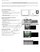
Hardware Interface Description
① Charging Slots (USB 2.0 Type A Plug)
Store, recharge and link microphones in the USB slots. Slots are
associated to channels in an APT according to the system setup in the
GUI.
② Power LED
Illuminates when the unit powered on.
③ Link LED
Illuminates after a successful link.
④ Link Button
Press and hold for 10 seconds to link all microphones in the charger to
channels of the associated APT.
⑤ Battery Status LEDs
Monitor microphone battery status during a charge, in increments of 10,
25, 50, 75, 100%
⑥ Locking DC Power Supply Jack
Screw the PS45 power supply to the input, illuminating the POWER LED.
⑦ Power Switch
Powers the unit on or off
⑧ Ethernet Port
Connects to the MXW system using a Cat5e (or higher) cable.
⑨ Network Status LED (Green)
•Off = no network link.
•On = sending or receiving digital audio over the network.
•Flashing = cannot establish a connection.
⑩ Network Speed LED (Amber)
•Off = 10 Mbps
•On = 100 Mbps
Networked Charger (NCS)
7
8
6
5
1
2
3
4
2 3 4
5
6
7 8
1
Link
Power
Link
Power
2
3 4
1
Charger Slots Correspond to Audio Channels
8-Channel Charger (NCS8) 4-Channel Charger (NCS4)
7
8
6
5
1
2
3
4
Link
Power
③
④
⑤
⑥
⑦
⑧
⑨
⑩
①
②
10/02/12