
Specifications


Stages in milling and drilling
ProtoMat 95s/II 51
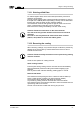
fig. 36:Top view of plotter head
4
6
8
3
7
1
2
5
9
10
11
1
- 6 bar compressed-air connection from
pneumatic system unit
7
- Base plate
2
- Extraction with connection
8
- Locating screw for working depth limiter
(here covered by 6)
3
- Pneumatic block with valves
9
- Pneumatic connection
4
- Z-axis guide
10
- Tapped hole for options
5
- Active auxiliary clamp
11
- Compressed air outlet (6 mm) to the
AutoContac cartridge (optional)
6
- High-frequency spindle with pneumatic-
cylinder