
Operator`s manual


84 918496/GP0313
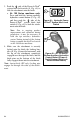
3. Push the side of the Power-A-Tach
®
system hitch lock switch (L, Fig. 48) to
lock the attachment onto the hitch.
a. AL 100 Series machines only:
Press and hold the bottom auxiliary
hydraulics control button (Z, Fig. 49)
and then push the side of the
Power-A-Tach
®
system hitch lock
switch (L, Fig. 48) to lock the attach-
ment onto the hitch.
Note: Due to ongoing product
improvement and variations during
production, it may be necessary to
hold the top auxiliary hydraulics
control button instead of the bottom
button to enable the hitch lock switch
on AL 100 Series machines.
4. Make sure the attachment is securely
locked onto the hitch: the locking han-
dles (K, Fig. 44) must be horizontal, with
the lip on the attachment completely
engaged over the top of the hitch, and the
hitch pins on the bottom of the hitch
fully engaged down into the attachment.
Note: 4-point hitch (EU only) locking pins
engage out through the sides of the attach-
ment.
Figure 48 – Hydraulic Power-
A-Tach
®
System Hitch Lock
Switch
L
Figure 49 – AL 100 Series
Bottom Auxiliary Hydraulics
Control Button (Power-A-
Tach® System Hitch Lock
Switch Enable Button)
Z