
Technical data


4. Service procedures
1
2
3
4
5
IV - 51
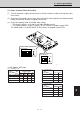
(11) Items to Check Prior to Test Run
(1) Turn on the power supply switch more than 5 hours before in order to charge the crank
case heater.
(2) Fully open the outdoor service valve after making the leak inspection of field connected
tubing, vacuuming, and gas charging if necessary.
(3) Check the capacity code and model code setting.
* The factory setting is as shown in the table. Double check it.
* The capacity code is set by S4 (green, 4P DIP switch) on outdoor control PCB.
The model code is set by S5 (black, 2P DIP switch) on outdoor control PCB.
1
ON
ON side
1577_C_I
OFF side
S4 (green or Blue) capacity code
(4P DIP switch)
2 3 4
1
ON
ON side
OFF side
S5 (black) model code
(2P DIP switch)
2
S5. Model code
• R407 Models: AER type
No. Outdoor PCB
Model No. 1 2 3 4
25 type (1 phase) ON ON ON OFF
25 type (3 phase) ON ON ON OFF
36 type (3 phase) OFF ON OFF ON
48 type (3 phase) OFF OFF ON ON
No. Outdoor PCB
Model No. 1 2
AER 425 SHLE
OFF ON
AER
425 SHL3E OFF OFF
AER
436 SHL3E OFF OFF
AER
448 SHL3E OFF OFF
S4. Capacity code
No. Outdoor PCB
Model No. 1 2
AER 425 SCLE ON ON
AER 425 SCL3E ON OFF
AER 436 SCL3E ON OFF
AER 448 SCL3E ON OFF
S5. Model code