AIRPLANE INFORMATION MANUAL for the CIRRUS DESIGN SR20 Aircraft Serials 1148 thru 1267 and Aircraft Serials 1005 thru 1147 after 3000 Pound Gross Weight Modification At the time of issuance, this Information Manual was harmonized with the SR20 Pilot's Operating Handbook Rev A10 (P/N 11934-002), and will not be kept current. Therefore, this Information Manual is for reference only and cannot be used as a substitute for the official Pilot's Operating Handbook and FAA Approved Airplane Flight Manual.
Copyright © 2011 - All Rights Reserved Cirrus Design Corporation 4515 Taylor Circle Duluth, MN 55811
Cirrus Design SR20 Section 1 General Section 1 General Table of Contents Introduction ..................................................................................... 1-3 The Airplane.................................................................................... 1-6 Engine.......................................................................................... 1-6 Propeller ...................................................................................... 1-6 Fuel...........................
Section 1 General Cirrus Design SR20 Intentionally Left Blank 1-2 P/N 13999-002 Info Manual September 2011
Cirrus Design SR20 Section 1 General Introduction This section contains information of general interest to pilots and owners. You will find the information useful in acquainting yourself with the airplane, as well as in loading, fueling, sheltering, and handling the airplane during ground operations. Additionally, this section contains definitions or explanations of symbols, abbreviations, and terminology used throughout this handbook.
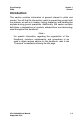
Section 1 General Cirrus Design SR20 26.0' 9.2' 7" NOTE: • Wing s pan includes position and strobe lights. • Prop ground clearance at 3000 lb - 7" (2 blade), 8" (3 blade). • Wing Area = 135.2 sq. ft. 35.5' 76" 2-BLADE 74" 3-BLADE 11.
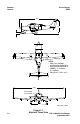
Cirrus Design SR20 Section 1 General GROUND TURNING CLEARANCE -RADIUS FOR WING TIP -RADIUS FOR NOSE GEAR 23' 11" 9' 11" 6" -RADIUS FOR INSIDE GEAR -RADIUS FOR OUTSIDE GEAR 12' 2" TURNING RADII ARE CALCULATED USING ONE BRAKE AND PARTIAL POWER. ACTUAL TURNING RADIUS MAY VARY AS MUCH AS THREE FEET.
Section 1 General Cirrus Design SR20 The Airplane Engine Number of Engines.............................................................................. 1 Number of Cylinders............................................................................ 6 Engine Manufacturer ........................................... Teledyne Continental Engine Model........................................................................ IO-360-ES Fuel Metering................................................................
Cirrus Design SR20 Section 1 General Fuel Total Capacity.............................................60.5 U.S. Gallons (229.0 L) Total Usable...................................................56 U.S. Gallons (212.0 L) Approved Fuel Grades: 100 LL Grade Aviation Fuel (Blue) 100 (Formerly 100/130) Grade Aviation Fuel (Green) Oil Oil Capacity (Sump) ............................................. 8 U.S. Quarts (7.6 L) Oil Grades: All Temperatures ............................................
Section 1 General Cirrus Design SR20 Symbols, Abbreviations and Terminology General Airspeed Terminology and Symbols KCAS Knots Calibrated Airspeed is the indicated airspeed corrected for position and instrument error. Calibrated airspeed is equal to true airspeed in standard atmosphere at sea level. KIAS Knots Indicated Airspeed is the speed shown on the airspeed indicator. The IAS values published in this handbook assume no instrument error.
Cirrus Design SR20 Section 1 General VSO Stalling Speed is the minimum steady flight speed at which the aircraft is controllable in the landing configuration (100% flaps) at the most unfavorable weight and balance. VX Best Angle of Climb Speed is the speed at which the airplane will obtain the highest altitude in a given horizontal distance. The best angle-of-climb speed normally increases slightly with altitude.
Section 1 General Cirrus Design SR20 • Pressure Altitude is the altitude read from the altimeter when the altimeter’s barometric adjustment has been set to 29.92 in.Hg (1013 mb) corrected for position and instrument error. In this Handbook, altimeter instrument errors are assumed to be zero. • Standard Temperature is the temperature that would be found at a given pressure altitude in the standard atmosphere. It is 15° C (59° F) at sea level pressure altitude and decreases approximately 2° C (3.
Cirrus Design SR20 Section 1 General NMPG Nautical Miles Per Gallon is the distance (in nautical miles) which can be expected per gallon of fuel consumed at a specific engine power setting and/or flight configuration. • Unusable Fuel is the quantity of fuel that cannot be safely used in flight. • Usable Fuel is the fuel available for flight planning. Weight and Balance Terminology c.g. Center of Gravity is the point at which an airplane would balance if suspended.
Section 1 General Cirrus Design SR20 • Station is a location along the airplane fuselage measured in inches from the reference datum and expressed as a number. For example: A point 123 inches aft of the reference datum is Fuselage Station 123.0 (FS 123). • Reference Datum is an imaginary vertical plane from which all horizontal distances are measured for balance purposes. • Tare is the weight of all items used to hold or position the airplane on the scales for weighing.
Cirrus Design SR20 Section 2 Limitations Section 2 Limitations Table of Contents Introduction ..................................................................................... 2-3 Certification Status .......................................................................... 2-3 Airspeed Limitations........................................................................ 2-4 Airspeed Indicator Markings ........................................................... 2-5 Power Plant Limitations .............
Section 2 Limitations Cirrus Design SR20 Intentionally Left Blank 2-2 P/N 13999-002 Info Manual September 2011
Cirrus Design SR20 Section 2 Limitations Introduction • Note • Limitations associated with optional equipment are not described in this section. For optional equipment limitations, refer to Section 9, Supplements The limitations included in this Section of the Pilot’s Operating Handbook (POH) are approved by the Federal Aviation Administration.
Section 2 Limitations Cirrus Design SR20 Airspeed Limitations The indicated airspeeds in the following table are based upon Section 5 Airspeed Calibrations using the normal static source. When using the alternate static source, allow for the airspeed calibration variations between the normal and alternate static sources. Speed KIAS KCAS VNE 200 200 Never Exceed Speed is the speed limit that may not be exceeded at any time.
Cirrus Design SR20 Section 2 Limitations Airspeed Indicator Markings The airspeed indicator markings are based upon Section 5 Airspeed Calibrations using the normal static source. When using the alternate static source, allow for the airspeed calibration variations between the normal and alternate static sources. Marking Value (KIAS) Remarks White Arc 56 - 100 Full Flap Operating Range. Lower limit is the most adverse stall speed in the landing configuration.
Section 2 Limitations Cirrus Design SR20 Power Plant Limitations Engine Teledyne Continental ............................................................ IO-360-ES Power Rating ........................................................ 200 hp @ 2700 rpm Maximum RPM .......................................................................2700 rpm Oil: Oil Temperature.................................... 240° F (115° C) maximum Oil Pressure: Minimum................................................................
Cirrus Design SR20 Section 2 Limitations Propeller • Note • Two-blade propellers are not EASA approved for use on this airplane. Airplanes registered in the European Union should ignore all references to the two-blade propeller in this POH. Hartzell Propeller Type ............................................................. Constant Speed Two-Blade Propeller: Model Number................................................... BHC-J2YF-1BF/F7694 Diameter........................................................
Section 2 Limitations Cirrus Design SR20 Instrument Markings Instrument (Range) Red Line Green Arc Yellow Arc Red Line Minimum Normal Caution Maximum Power Plant Instrumentation Tachometer (0 - 3500 RPM) –– 500 - 2700 –– 2700 Cylinder Head Temperature (200° F - 500° F) –– 240° - 420° F 420° - 460° F 460° F Exhaust Gas Temp. (1250° - 1650° F) –– –– –– –– Manifold Pressure (10 – 35 Inches Hg) –– 15 - 29.5 in. Hg 29.5 – 35 in. Hg –– Fuel Flow (0 – 18 U.S. Gal./ Hr.
Cirrus Design SR20 Section 2 Limitations Center of Gravity Limits Reference Datum ....................................100 inches forward of firewall Forward ................................................................... Refer to Figure 2-4 Aft ............................................................................ Refer to Figure 2-4 23.1 % MAC FS 144.1 3000 lb 3000 31.3 % MAC FS 148.0 3000 lb Weight - Pounds 2800 31.5 % MAC FS 148.1 2900 lb 16.7 % MAC FS 141.0 2694 lb 2600 30.
Section 2 Limitations Cirrus Design SR20 Maneuver Limits Aerobatic maneuvers, including spins, are prohibited. • Note • Because the SR20 has not been certified for spin recovery, the Cirrus Airframe Parachute System (CAPS) must be deployed if the airplane departs controlled flight. Refer to Section 3 – Emergency Procedures, Inadvertent Spiral/Spin Entry. This airplane is certified in the normal category and is not designed for aerobatic operations.
Cirrus Design SR20 Section 2 Limitations Kinds of Operation The SR20 is equipped and approved for the following type operations: • VFR day and night. • IFR day and night. Kinds of Operation Equipment List The following listing summarizes the equipment required under Federal Aviation Regulations (FAR) Part 23 for airworthiness under the listed kind of operation. Those minimum items of equipment necessary under the operating rules are defined in FAR Part 91 and FAR Part 135 as applicable.
Section 2 Limitations System, Instrument, and/or Equipment Cirrus Design SR20 Kinds of Operation VFR Day VFR Nt. IFR Day IFR Nt.
Cirrus Design SR20 System, Instrument, and/or Equipment Section 2 Limitations Kinds of Operation VFR Day VFR Nt. IFR Day IFR Nt.
Section 2 Limitations System, Instrument, and/or Equipment Cirrus Design SR20 Kinds of Operation VFR Day VFR Nt. IFR Day IFR Nt.
Cirrus Design SR20 Section 2 Limitations Taxi Power Maximum continuous engine speed for taxiing is 1000 RPM on flat, smooth, hard surfaces. Power settings slightly above 1000 RPM are permissible to start motion, for turf, soft surfaces, and on inclines. Use minimum power to maintain taxi speed.
Section 2 Limitations Cirrus Design SR20 Systems and Equipment Limits Cirrus Airframe Parachute System (CAPS) VPD Maximum Demonstrated Deployment Speed..................135 KIAS • Note • Refer to Section 10 – Safety Information, for additional CAPS guidance. Multi-Function Display 1. The moving map display must not be used as the primary navigation instrument. The moving map display provides visual advisory of the airplane’s GPS position against a moving map.
Cirrus Design SR20 Section 2 Limitations dated May 1998 or later revision, must be available to the pilot during all flight operations 7. Serials with Avidyne MFD installed: The Avidyne FlightMax EX5000C Pilot’s Guide, P/N 600-00108-000, Revision 03 or later, must be available to the pilot during all flight operations.
Section 2 Limitations Cirrus Design SR20 Other Limitations Smoking Smoking is prohibited in this airplane.
Cirrus Design SR20 Section 2 Limitations Placards Engine compartment, inside oil filler access: ENGINE OIL GRADE ABOVE 40° F SAE 50 OR 20W50 BELOW 40° F SAE 30 OR 10W30, 15W50, OR 20W50 REFER TO AFM FOR APPROVED OILS Wing, adjacent to fuel filler caps: AVGAS MIN GRADE 100LL OR 100 28 U.S. GALS. TOTAL USABLE CAP 13 U.S. GALS. USABLE TO TAB Serials 1005 thru 1099. AVGAS MIN GRADE 100LL OR 100 28 U.S. GALS. (106 LITERS) TOTAL USABLE CAP 13 U.S. GALS. (49 LITERS) USABLE TO TAB Serials 1100 thru 1326.
Section 2 Limitations Cirrus Design SR20 Upper fuselage, either side of CAPS rocket cover: WARNING! ROCKET FOR PARACHUTE DEPLOYMENT INSIDE STAY CLEAR WHEN AIRPLANE IS OCCUPIED Left fuselage, on external power supply door: EXTERNAL Rudder, and elevator, both sides: NO PUSH POWER 28 V DC Doors, above and below latch: C L O SE CLOSE O P OPEN E N Serials 1317 thru 1422. Serials 1005 thru 1316. PUSH TO OPEN Serials 1423 & subs.
Cirrus Design SR20 Section 2 Limitations Engine control panel: UP UP 50% 50% 120 KIAS FLAPS FLAPS 100% 100% 100 KIAS Airplane serials 1020 and subsequent and airplane serials 1005 thru 1019 incorporating SB 20-11-01. OPEN T H R O T T L E BOOST FUEL PUMP PRIME IDLE RICH M I X T U R E OPEN F R I C T I O N BOOST FUEL PUMP LEAN PRIME LEFT 28 GALLONS USABLE T H R O T T L E IDLE FULL RICH M I X T U R E F R I C T I O N CUTOFF RIGHT 28 GALLONS USABLE LEFT 28 U.S.
Section 2 Limitations Cirrus Design SR20 Engine control panel (cont): UP FLAPS UP 50% 50% 120 KIAS 120 KIAS FLAPS 100% 100% 100 KIAS 100 KIAS CREW SEATS MUST BE LOCKED IN POSITION AND CONTROL HANDLES FULLY DOWN BEFORE FLIGHT MAX FULL RICH P I O X W BOOST E T U R FUEL PUMP R PRIME IDLE LEFT 28 GALLONS USABLE FULL RICH P F R I C T I O N I X W BOOST E R PRIME IDLE LEFT 28 GALLONS USABLE F R I C T I O N E CUTOFF RIGHT 28 GALLONS USABLE OFF 11113-005 T U R FUEL PUMP CUTO
Cirrus Design SR20 Section 2 Limitations Wing, flap aft edge: NO STEP Cabin Door Window, lower edge, centered, applied upside down: RESCUE: FRACTURE AND REMOVE WINDOW Bolster Switch Panel, left edge: THIS AIRCRAFT IS CERTIFIED FOR THE FOLLOWING FLIGHT OPERATIONS: DAY - NIGHT - VFR - IFR (WITH REQUIRED EQUIPMENT) FLIGHT INTO KNOWN ICING IS PROHIBITED OPERATE PER AIRPLANE FLIGHT MANUAL Serials 1005 & subs w/o SRV option.
Section 2 Limitations Cirrus Design SR20 Bolster Panel, both sides: GRAB HERE Serials 1351 & subs. Instrument Panel: NO SMOKING FASTEN SEATBELTS FIRE EXTINGUISHER UNDER PILOT SEAT FRONT Serials 1005 thru 1638. FASTEN SEAT BELT • NO SMOKING FIRE EXTINGUISHER FORWARD LEFT OF PILOT SEAT Serials 1639 & subs. Cabin Window, above door latch: EMERGENCY EXIT REMOVE EGRESS HAMMER FROM ARMREST LID STRIKE CORNER OF WINDOW, KICK OR PUSH OUT AFTER FRACTURING Serials 1005 thru 1178.
Cirrus Design SR20 Section 2 Limitations Baggage Compartment, aft edge: ELT LOCATED BEHIND BULKHEAD REMOVE CARPET AND ACCESS PANEL Baggage Compartment Door, inside: DISTRIBUTED FLOOR LIMIT 130 LBS BAGGAGE STRAP CAPACITY IS 35 LBS EACH MAXIMUM SEE AIRPLANE FLIGHT MANUAL FOR BAGGAGE TIE-DOWN AND WEIGHT AND BALANCE INFORMATION 12378-001 REV A SR20_FM02_1224 P/N 13999-002 Info Manual September 2011 Figure 2-5 Placards (Sheet 7 of 9) 2-25
Section 2 Limitations Cirrus Design SR20 CAPS Deployment Handle Cover, above pilot's right shoulder: ! WARNING THIS AIRCRAFT IS EQUIPPED WITH A C.A.P.S. PARACHUTE RECOVERY SYSTEM USE FOR EXTREME EMERGENCIES ONLY SEAT BELT AND SHOULDER HARNESS MUST BE WORN AT ALL TIMES USE OF THIS DEVICE COULD RESULT IN INJURY OR DEATH MAXIMUM DEMONSTRATED DEPLOYMENT SPEED 135 KIAS Serials 1100 thru 1195 before SB 20-95-03. ACTIVATION PROCEDURES 1. FUEL MIXTURE...........................IDLE CUT-OFF 2. THIS COVER.....
Cirrus Design SR20 Section 2 Limitations CAPS Deployment Handle Cover, above pilot's right shoulder: ! WARNING USE FOR EXTREME EMERGENCIES ONLY SEAT BELT AND SHOULDER HARNESS MUST BE WORN AT ALL TIMES USE OF THIS DEVICE COULD RESULT IN INJURY OR DEATH MAXIMUM DEMONSTRATED DEPLOYMENT SPEED 135 KIAS CIRRUS AIRFRAME PARACHUTE SYSTEM ACTIVATION PROCEDURE 1. FUEL MIXTURE.......................................CUT-OFF 2. THIS COVER............................................REMOVE 3. ACTIVATION HANDLE.......
Section 2 Limitations Cirrus Design SR20 Intentionally Left Blank 2-28 P/N 13999-002 Info Manual September 2011
Cirrus Design SR20 Section 3 Emergency Procedures Section 3 Emergency Procedures Table of Contents Introduction ..................................................................................... 3-3 Airspeeds for Emergency Operations ............................................. 3-4 Emergency Procedures Guidance .................................................. 3-5 Preflight Planning......................................................................... 3-5 Preflight Inspections/Maintenance ........
Section 3 Emergency Procedures Cirrus Design SR20 Vacuum System Failure.............................................................
Cirrus Design SR20 Section 3 Emergency Procedures Introduction This section provides procedures for handling emergencies and critical flight situations that may occur while operating the SR20. Although emergencies caused by airplane, systems, or engine malfunctions are extremely rare, the guidelines described in this section should be considered and applied as necessary should an emergency arise. • Note • Emergency procedures associated with optional systems can be found in Section 9.
Section 3 Emergency Procedures Cirrus Design SR20 Airspeeds for Emergency Operations Maneuvering Speed: 3000 lb .............................................................................131 KIAS 2600 lb .............................................................................122 KIAS 2200 lb .............................................................................111 KIAS Best Glide: 3000 lb ...............................................................................96 KIAS 2500 lb .........
Cirrus Design SR20 Section 3 Emergency Procedures Emergency Procedures Guidance Although this section provides procedures for handling most emergencies and critical flight situations that could arise in the SR20, it is not a substitute for thorough knowledge of the airplane and general aviation techniques. A thorough study of the information in this handbook while on the ground will help you prepare for time-critical situations in the air.
Section 3 Emergency Procedures Cirrus Design SR20 Take Appropriate Action — In most situations, the procedures listed in this section will either correct the aircraft problem or allow safe recovery of the aircraft. Follow them and use good pilot judgment. The Cirrus Airframe Parachute System (CAPS) should be activated in the event of a life-threatening emergency where CAPS deployment is determined to be safer than continued flight and landing.
Cirrus Design SR20 Section 3 Emergency Procedures Ground Emergencies Engine Fire During Start A fire during engine start may be caused by fuel igniting in the fuel induction system. If this occurs, attempt to draw the fire back into the engine by continuing to crank the engine. 1. Mixture ..............................................................................CUTOFF 2. Fuel Pump ............................................................................... OFF 3. Fuel Selector......................
Section 3 Emergency Procedures Cirrus Design SR20 Emergency Ground Egress • WARNING • While exiting the airplane, make sure evacuation path is clear of other aircraft, spinning propellers, and other hazards. 1. Engine........................................................................SHUTDOWN • Note • If the engine is left running, set the Parking Brake prior to evacuating the airplane. 2. Seat belts ....................................................................... RELEASE 3. Airplane...........
Cirrus Design SR20 Section 3 Emergency Procedures In-Flight Emergencies Engine Failure On Takeoff (Low Altitude) If the engine fails immediately after becoming airborne, abort on the runway if possible. If altitude precludes a runway stop but is not sufficient to restart the engine, lower the nose to maintain airspeed and establish a glide attitude. In most cases, the landing should be made straight ahead, turning only to avoid obstructions.
Section 3 Emergency Procedures Cirrus Design SR20 Maximum Glide Conditions Example: Power Propeller Flaps Wind OFF Windmilling 0% (UP) Zero Altitude Airspeed 7,000 ft. AGL Best Glide Glide Distance 12.5 NM Best Glide Speed 3000 lb 96 KIAS 2500 lb 87 KIAS Maximum Glide Ratio ~ 10.
Cirrus Design SR20 Section 3 Emergency Procedures Engine Failure In Flight If the engine fails at altitude, pitch as necessary to establish best glide speed. While gliding toward a suitable landing area, attempt to identify the cause of the failure and correct it. If altitude or terrain does not permit a safe landing, CAPS deployment may be required. Refer to Section 10, Safety Information, for CAPS deployment scenarios and landing considerations.
Section 3 Emergency Procedures Cirrus Design SR20 Engine Airstart The following procedures address the most common causes for engine loss. Switching tanks and turning the fuel pump on will enhance starting if fuel contamination was the cause of the failure. Leaning the mixture and then slowly enriching mixture may correct faulty mixture control. • Note • Engine airstarts may be performed during 1g flight anywhere within the normal operating envelope of the airplane. 1. Bat Master Switch ..................
Cirrus Design SR20 Section 3 Emergency Procedures Engine Partial Power Loss Indications of a partial power loss include fluctuating RPM, reduced or fluctuating manifold pressure, low oil pressure, high oil temperature, and a rough-sounding or rough-running engine. Mild engine roughness in flight may be caused by one or more spark plugs becoming fouled. A sudden engine roughness or misfiring is usually evidence of a magneto malfunction.
Section 3 Emergency Procedures Cirrus Design SR20 The following procedure provides guidance to isolate and correct some of the conditions contributing to a rough running engine or a partial power loss: 1. Fuel Pump.......................................................................... BOOST Selecting BOOST on may clear the problem if vapor in the injection lines is the problem or if the engine-driven fuel pump has partially failed.
Cirrus Design SR20 Section 3 Emergency Procedures Low Oil Pressure If low oil pressure is accompanied by a rise in oil temperature, the engine has probably lost a significant amount of its oil and engine failure may be imminent. Immediately reduce engine power to idle and select a suitable forced landing field. • WARNING • Prolonged use of high power settings after loss of oil pressure will lead to engine mechanical damage and total engine failure, which could be catastrophic.
Section 3 Emergency Procedures Cirrus Design SR20 Smoke and Fume Elimination If smoke and/or fumes are detected in the cabin, check the engine parameters for any sign of malfunction. If a fuel leak has occurred, actuation of electrical components may cause a fire. If there is a strong smell of fuel in the cockpit, divert to the nearest suitable landing field. Perform a Forced Landing pattern and shut down the fuel supply to the engine once a safe landing is assured. 1. Heater .............................
Cirrus Design SR20 Section 3 Emergency Procedures Cabin Fire In Flight If the cause of the fire is readily apparent and accessible, use the fire extinguisher to extinguish flames and land as soon as possible. Opening the vents or doors may feed the fire, but to avoid incapacitating the crew from smoke inhalation, it may be necessary to rid cabin of smoke or fire extinguishant. If the cause of fire is not readily apparent, is electrical, or is not readily accessible, proceed as follows: 1.
Section 3 Emergency Procedures Cirrus Design SR20 switches OFF. Do not attempt to isolate the source of the fire by checking each individual electrical component. 10. Bat-Alt Master Switches ............................................................ ON 11. Avionics Power Switch .............................................................. ON 12. Activate required systems one at a time. Pause several seconds between activating each system to isolate malfunctioning system.
Cirrus Design SR20 Section 3 Emergency Procedures Spins The SR20 is not approved for spins, and has not been tested or certified for spin recovery characteristics. The only approved and demonstrated method of spin recovery is activation of the Cirrus Airframe Parachute System (See CAPS Deployment, this section). Because of this, if the aircraft “departs controlled flight”, the CAPS must be deployed.
Section 3 Emergency Procedures Cirrus Design SR20 CAPS Deployment The Cirrus Airframe Parachute System (CAPS) should be activated in the event of a life-threatening emergency where CAPS deployment is determined to be safer than continued flight and landing.
Cirrus Design SR20 Section 3 Emergency Procedures The maximum demonstrated deployment speed is 135 KIAS. Reducing airspeed allows minimum parachute loads and prevents structural overload and possible parachute failure. 2. Mixture (If time and altitude permit) ..................................CUTOFF Generally, a distressed airplane will be safer for its occupants if the engine is not running. 3. Activation Handle Cover...................................................
Section 3 Emergency Procedures Cirrus Design SR20 All occupants must have seat belts and shoulder harness securely fastened. 12. Loose Items ..................................................................... SECURE If time permits, all loose items should be secured to prevent injury from flying objects in the cabin at touchdown. 13. Assume emergency landing body position.
Cirrus Design SR20 Section 3 Emergency Procedures Landing Emergencies If all attempts to restart the engine fail and a forced landing is imminent, select a suitable field and prepare for the landing. If flight conditions or terrain does not permit a safe landing, CAPS deployment may be required. Refer to Section 10, Safety Information, for CAPS deployment scenarios and landing considerations.
Section 3 Emergency Procedures Cirrus Design SR20 Ditching 1. Radio............................................. Transmit (121.5 MHz) MAYDAY giving location and intentions 2. Transponder ........................................................... SQUAWK 7700 3. CAPS ............................................................................. ACTIVATE If available, life preservers should be donned and life raft should be prepared for immediate evacuation upon touchdown.
Cirrus Design SR20 Section 3 Emergency Procedures Landing Without Elevator Control The pitch trim spring cartridge is attached directly to the elevator and provides a backup should you lose the primary elevator control system. Set elevator trim for a 80 KIAS approach to landing. Thereafter, do not change the trim setting until in the landing flare. During the flare, the nose-down moment resulting from a power reduction may cause the airplane to hit on the nosewheel.
Section 3 Emergency Procedures Cirrus Design SR20 System Malfunctions Power Lever Linkage Failure If the Power Lever linkage fails in flight, the engine will not respond to power lever control movements. Use power available and flaps as required to safely land the airplane. If the power lever is stuck at or near the full power position, proceed to a suitable airfield. Fly a forced landing pattern. With landing assured, shut down engine by moving mixture control full aft to CUTOFF.
Cirrus Design SR20 Section 3 Emergency Procedures Vacuum System Failure Failure of the engine driven vacuum pump is indicated by illumination of the red VACUUM warning light. If the engine driven vacuum pump fails, the electric standby vacuum pump will automatically energize and the amber AUX VAC caution light will illuminate indicating that the electric pump is operating and supplying vacuum for instrument operation.
Section 3 Emergency Procedures Cirrus Design SR20 Intentionally Left Blank 3-28 P/N 13999-002 Info Manual September 2011
Cirrus Design SR20 Section 3A Abnormal Procedures Section 3A Abnormal Procedures Table of Contents Introduction .................................................................................. 3A-3 Abnormal Procedures Guidance .................................................. 3A-4 Ground Procedures...................................................................... 3A-5 Brake Failure During Taxi ......................................................... 3A-5 Aborted Takeoff ...........................
Section 3A Abnormal Procedures Cirrus Design SR20 Intentionally Left Blank 3A-2 P/N 13999-002 Info Manual September 2011
Cirrus Design SR20 Section 3A Abnormal Procedures Introduction This section provides procedures for handling abnormal system and/or flight conditions which, if followed, will maintain an acceptable level of airworthiness or reduce operational risk. The guidelines described in this section are to be used when an abnormal condition exists and should be considered and applied as necessary.
Section 3A Abnormal Procedures Cirrus Design SR20 Abnormal Procedures Guidance Although this section provides procedures for handling most abnormal system and/or flight conditions that could arise in the SR20, it is not a substitute for thorough knowledge of the airplane and general aviation techniques. A thorough study of the information in this handbook while on the ground will help you prepare for time-critical situations in the air.
Cirrus Design SR20 Section 3A Abnormal Procedures Ground Procedures Brake Failure During Taxi Ground steering is accomplished by differential braking. However, increasing power may allow some rudder control due to increased groundspeed and airflow over the rudder. 1. Engine Power......................................................... AS REQUIRED • To stop airplane - REDUCE • If necessary for steering - INCREASE 2. Directional Control ............................... MAINTAIN WITH RUDDER 3.
Section 3A Abnormal Procedures Cirrus Design SR20 In-Flight Procedures Inadvertent Icing Encounter Flight into known icing conditions is prohibited. However, If icing is inadvertently encountered: 1. Pitot Heat .................................................................................. ON 2. Exit icing conditions. Turn back or change altitude. 3. Cabin Heat .................................................................... MAXIMUM 4. Windshield Defrost ............................................
Cirrus Design SR20 Section 3A Abnormal Procedures Landing Procedures Landing With Failed Brakes One brake inoperative 1. Land on the side of runway corresponding to the inoperative brake. 2. Maintain directional control using rudder and working brake. Both brakes inoperative 1. Divert to the longest, widest runway with the most direct headwind. 2. Land on downwind side of the runway. 3. Use the rudder for obstacle avoidance. • Note • Rudder effectiveness will decrease with decreasing airspeed. 4.
Section 3A Abnormal Procedures Cirrus Design SR20 System Malfunctions Alternator Failure Abnormal ammeter indications and illumination of the LOW VOLTS warning light may indicate electrical power supply system malfunctions. A broken alternator drive belt, wiring fault or a defective alternator control unit is most likely the cause of the alternator failure. Usually, electrical power malfunctions are indicated by an excessive rate of charge or a discharge rate.
Cirrus Design SR20 Section 3A Abnormal Procedures should be completed. Battery power must be conserved for later operation of the wing flaps, lights, and other essential equipment. • Note • Ammeter discharge indications and illumination of the LOW VOLTS warning light can occur during low RPM conditions with a heavy electrical load, such as during taxi. Under these conditions, the master switch need not be cycled as an overvoltage condition has not occurred and the alternator was not de-activated.
Section 3A Abnormal Procedures Cirrus Design SR20 Communications Failure Communications failure can occur for a variety of reasons. If, after following the checklist procedure, communication is not restored, proceed with FAR/AIM lost communications procedures. • Note • In the event of an audio panel power failure the audio panel connects COM 1 to the pilot’s headset and speakers. Setting the audio panel ‘Off’ will also connect COM 1 to the pilot’s headsets and speakers. 1. Switches, Controls .............
Cirrus Design SR20 Section 3A Abnormal Procedures Pitot Static Malfunction Static Source Blocked If erroneous readings of the static source instruments (airspeed, altimeter and vertical speed) are suspected, the alternate static source valve, on side of console near pilot’s right ankle, should be opened to supply static pressure from the cabin to these instruments.
Section 3A Abnormal Procedures Cirrus Design SR20 Electric Trim/Autopilot Failure Any failure or malfunction of the electric trim or autopilot can be overridden by use of the control yoke. If runaway trim is the problem, deenergize the circuit by pulling the circuit breaker (PITCH TRIM, ROLL TRIM, or AUTOPILOT) and land as soon as conditions permit. 1. Airplane Control ......................................... MAINTAIN MANUALLY 2. Autopilot (if engaged) ....................................................
Cirrus Design SR20 Section 4 Normal Procedures Section 4 Normal Procedures Table of Contents Introduction ..................................................................................... 4-3 Airspeeds for Normal Operation ..................................................... 4-4 Normal Procedures ......................................................................... 4-5 Preflight Inspection ......................................................................4-5 Preflight Walk-Around ............
Section 4 Normal Procedures Cirrus Design SR20 Intentionally Left Blank 4-2 P/N 13999-002 Info Manual September 2011
Cirrus Design SR20 Section 4 Normal Procedures Introduction This section provides amplified procedures for normal operation. Normal procedures associated with optional systems can be found in Section 9.
Section 4 Normal Procedures Cirrus Design SR20 Airspeeds for Normal Operation Unless otherwise noted, the following speeds are based on a maximum weight of 3000 lb. and may be used for any lesser weight. However, to achieve the performance specified in Section 5 for takeoff distance, the speed appropriate to the particular weight must be used. Takeoff Rotation: • Normal, Flaps 50% ........................................................67 KIAS • Short Field, Flaps 50% .....................................
Cirrus Design SR20 Section 4 Normal Procedures Normal Procedures Preflight Inspection Before carrying out preflight inspections, ensure that all required maintenance has been accomplished. Review your flight plan and compute weight and balance.
Section 4 Normal Procedures Cirrus Design SR20 Preflight Walk-Around 1. Cabin a. Required Documents................................................ On Board b. Avionics Power Switch.......................................................OFF c. Bat 2 Master Switch ........................................................... ON d. Avionics Cooling Fan .................................................... Audible e. Voltmeter ................................................................ 23-25 Volts f.
Cirrus Design SR20 Section 4 Normal Procedures e. Baggage Door ........................................... Closed and Secure f. Static Button .............................................. Check for Blockage g. Parachute Cover........................................ Sealed and Secure 3. Empennage a. Tiedown Rope .............................................................Remove b. Horizontal and Vertical Stabilizers.............................
Section 4 Normal Procedures c. Cirrus Design SR20 Fuel Drains (2 underside) ............................ Drain and Sample d. Wheel Fairings...................... Security, Accumulation of Debris e. Tire ............................................Condition, Inflation, and Wear • Note • Serials 1005 through 1592 after Service Bulletin SB 2X-32-14 and airplane serials 1593 and subsequent: Clean and inspect temperature indicator installed to piston housing.
Cirrus Design SR20 Section 4 Normal Procedures 10. Nose, Left Side a. Landing Light............................................................. Condition b. Engine Oil......... Check 6-8 quarts, Leaks, Cap & Door Secure c. Cowling.....................................................Attachments Secure d. External Power ..................................................... Door Secure e. Exhaust Pipe .....................Condition, Security, and Clearance 11. Left Main Gear and Forward Wing a.
Section 4 Normal Procedures Cirrus Design SR20 Before Starting Engine 1. Preflight Inspection .................................................. COMPLETED • WARNING • Ensure that the airplane is properly loaded and within the AFM’s weight and balance limitations prior to takeoff. 2. Weight and Balance ............................................Verify within limits 3. Emergency Equipment.................................................ON BOARD 4. Passengers ................................................
Cirrus Design SR20 Section 4 Normal Procedures Starting Engine If the engine is warm, no priming is required. For the first start of the day and in cold conditions, prime will be necessary. Weak intermittent firing followed by puffs of black smoke from the exhaust stack indicates over-priming or flooding. Excess fuel can be cleared from the combustion chambers by the following procedure: • Turn fuel pump off. • Allow fuel to drain from intake tubes.
Section 4 Normal Procedures Cirrus Design SR20 3. Bat Master Switch ............................................... ON (Check Volts) 4. Strobe Lights ............................................................................. ON 5. Vacuum System ................................................................. CHECK a. VACUUM Annunciator ........................................................ ON b. AUX Vac Annunciator ..................................ON (Pump Green) c. Suction Gage.................
Cirrus Design SR20 Section 4 Normal Procedures 15. Alt Master Switches ...................................................................ON 16. Avionics Power Switch ...............................................................ON 17. Engine Parameters ........................................................ MONITOR 18. External Power (If applicable) ................................. DISCONNECT 19. Amp Meter/Indication ......................................................... CHECK Before Taxiing 1.
Section 4 Normal Procedures Cirrus Design SR20 Before Takeoff During cold weather operations, the engine should be properly warmed up before takeoff. In most cases this is accomplished when the oil temperature has reached at least 100° F (38° C). In warm or hot weather, precautions should be taken to avoid overheating during prolonged ground engine operation. Additionally, long periods of idling may cause fouled spark plugs.
Cirrus Design SR20 Section 4 Normal Procedures 16. Pitot Heat ............................................................... AS REQUIRED • Note • Pitot Heat should be turned ON for flight into IMC, flight into visible moisture, or whenever ambient temperatures are 41° F (5° C) or less. 17. Navigation Lights ................................................... AS REQUIRED 18. Landing Light ......................................................... AS REQUIRED 19. Magnetos ...................................
Section 4 Normal Procedures Cirrus Design SR20 Takeoff • Note • The engine is equipped with an altitude compensating fuel pump that automatically provides the proper full rich mixture. Because of this, the mixture should be left full rich for takeoff, even at high altitude airfields. Power Check: Check full-throttle engine operation early in takeoff run. The engine should run smoothly and turn approximately 2700 RPM. All engine parameters should read in the green.
Cirrus Design SR20 Section 4 Normal Procedures Normal Takeoff 1. Brakes.................................... RELEASE (Steer with Rudder Only) 2. Power Lever ........................................................ FULL FORWARD 3. Engine Parameters ............................................................ CHECK 4. Elevator Control ........................ ROTATE Smoothly at 65-70 KIAS 5. At 85 KIAS, Flaps....................................................................... UP Short Field Takeoff 1.
Section 4 Normal Procedures Cirrus Design SR20 Climb Normal climbs are performed flaps UP (0%) and full power at speeds 5 to 10 knots higher than best rate-of-climb speeds. These higher speeds give the best combination of performance, visibility and engine cooling. For maximum rate of climb, use the best rate-of-climb speeds shown in the rate-of-climb chart in Section 5. If an obstruction dictates the use of a steep climb angle, the best angle-of-climb speed should be used.
Cirrus Design SR20 Section 4 Normal Procedures Cruise Normal cruising is performed between 55% and 75% power. The engine power setting and corresponding fuel consumption for various altitudes and temperatures can be determined by using the cruise data in Section 5. The selection of cruise altitude is made on the basis of the most favorable wind conditions and the use of low power settings. These significant factors should be considered on every trip to reduce fuel consumption.
Section 4 Normal Procedures Cirrus Design SR20 Cruise Leaning The engine is equipped with an altitude compensating fuel pump that automatically provides the proper full rich mixture. Because of this, the mixture should be set to full rich to allow the aneroid to provide auto leaning for the engine during all flight conditions. If additional cruise leaning beyond that provided by the aneroid is desired, be advised that there may not be a 75° temperature rise from full rich to peak.
Cirrus Design SR20 Section 4 Normal Procedures Descent 1. Altimeter................................................................................... SET 2. Cabin Heat/Defrost ................................................ AS REQUIRED 3. Landing Light .............................................................................ON 4. Fuel System ....................................................................... CHECK 5. Mixture ...................................................................
Section 4 Normal Procedures Cirrus Design SR20 Short Field Landing For a short field landing in smooth air conditions, make an approach at 75 KIAS with full flaps using enough power to control the glide path (slightly higher approach speeds should be used under turbulent air conditions). After all approach obstacles are cleared, progressively reduce power and maintain the approach speed by lowering the nose of the airplane. Touchdown should be made power-off and on the main wheels first.
Cirrus Design SR20 Section 4 Normal Procedures After Landing 1. Power Lever ................................................................... 1000 RPM 2. Fuel Pump ............................................................................... OFF 3. Flaps .......................................................................................... UP 4. Transponder ...........................................................................STBY 5. Lights ....................................................
Section 4 Normal Procedures Cirrus Design SR20 Stalls SR20 stall characteristics are conventional. Power-off stalls may be accompanied by a slight nose bobbing if full aft stick is held. Power-on stalls are marked by a high sink rate at full aft stick. Power-off stall speeds at maximum weight for both forward and aft C.G. positions are presented in Section 5 – Performance Data.
Cirrus Design SR20 Section 4 Normal Procedures Environmental Considerations Cold Weather Operation Starting If the engine has been cold soaked, it is recommended that the propeller be pulled through by hand several times to break loose or limber the oil. This procedure will reduce power draw on the battery if a battery start is made.
Section 4 Normal Procedures Cirrus Design SR20 Hot air must be applied directly to the oil sump and external oil lines as well as the cylinders, air intake and oil cooler. Because excessively hot air can damage non-metallic components such as composite parts, seals, hoses, and drives belts, do not attempt to hasten the preheat process. 1. Ignition Switch ..........................................................................OFF • WARNING • Use extreme caution when pulling the propeller through by hand.
Cirrus Design SR20 Section 4 Normal Procedures (Continued on following page) 11. Power Lever ............................................................ OPEN ¼ INCH 12. Ignition Switch....................... START (Release after engine starts) • Caution • Limit cranking to intervals of 20 seconds with a 20 second cooling period between cranks. This will improve battery and contactor life 13. Power Lever ...............................RETARD (to maintain 1000 RPM) 14. Oil Pressure ........................
Section 4 Normal Procedures Cirrus Design SR20 Noise Characteristics/Abatement The certificated noise levels for the Cirrus Design SR20 established in accordance with FAR 36 Appendix G are: Configuration Actual Maximum Allowable Two-blade Propeller 84.79 dB(A) 87.6 dB(A) Three-blade Propeller 83.42 dB(A) 87.
Cirrus Design SR20 Section 5 Performance Data Section 5 Performance Data Table of Contents Introduction ..................................................................................... 5-3 Associated Conditions Affecting Performance............................. 5-3 Flight Planning ................................................................................ 5-4 Sample Problem ............................................................................. 5-4 Takeoff..................................
Section 5 Performance Data Cirrus Design SR20 Range / Endurance Profile ............................................................5-29 Range / Endurance Profile ............................................................5-30 Balked Landing Climb Gradient ....................................................5-31 Balked Landing Rate of Climb.......................................................5-32 Landing Distance ..........................................................................
Cirrus Design SR20 Section 5 Performance Data Introduction Performance data in this section are presented for operational planning so that you will know what performance to expect from the airplane under various ambient and field conditions. Performance data are presented for takeoff, climb, and cruise (including range & endurance).
Section 5 Performance Data Cirrus Design SR20 Flight Planning The performance tables in this section present sufficient information to predict airplane performance with reasonable accuracy. However, variations in fuel metering, mixture leaning technique, engine & propeller condition, air turbulence, and other variables encountered during a particular flight may account for variations of 10% or more in range and endurance.
Cirrus Design SR20 Section 5 Performance Data Cruise Conditions: • Total distance ................................................560 Nautical Miles • Pressure altitude ........................................................ 6500 Feet • Temperature ...............................................20° C (ISA + 17° C) • Expected wind enroute..................................10 Knot Headwind Landing Conditions: • Field pressure altitude ................................................
Section 5 Performance Data Cirrus Design SR20 • Decrease in total distance (2734 feet x 0.092) .............. 252 feet • Corrected total distance to clear 50-foot obstacle ....... 2482 feet Corrections for grass runways and sloped runways are also applicable and should be applied. These corrections are calculated in the same manner as the wind correction above. Refer to Figure 5-9 for correction factors to be applied.
Cirrus Design SR20 Section 5 Performance Data climb performance is to increase the time, fuel, and distance to climb by approximately 10% for each 10° C above ISA. In our example, using a temperature of ISA + 13° C, the correction to be applied is 13%. The fuel estimate for climb is: • Fuel to climb (standard temperature) ............................ 2.1 Gal. • Increase due to non-standard temp. (2.1 x 0.13) .......... 0.3 Gal. • Corrected fuel to climb (2.1 + 0.3) ................................. 2.
Section 5 Performance Data Cirrus Design SR20 Fuel Required The total fuel requirement for the flight may be estimated using the performance information obtained from Figures 5-15 and 5-16. The resultant cruise distance is: • Total distance (from sample problem) ........................ 560.0 NM • Climb distance (corrected value from climb table)........ 17.0 NM • Cruise distance (total distance – climb distance) ....... 543.
Cirrus Design SR20 Section 5 Performance Data Landing A procedure similar to takeoff should be used for estimating the landing distance at the destination airport. Figure 5-20 presents landing distance information for the short field technique. The distances corresponding to 2000 feet and 20° C are as follows: • Ground roll ................................................................. 1110 Feet • Total distance to land over a 50-foot obstacle ...........
Section 5 Performance Data Cirrus Design SR20 Airspeed Calibration Normal Static Source Conditions: Example: • Power for level flight or maximum continuous, whichever is less. • Weight .................................. 3000 LB Flaps ........................................... 50% Indicated Airspeed ............... 85 Knots Calibrated Airspeed ............. 86 Knots • Note • • Indicated airspeed values assume zero instrument error.
Cirrus Design SR20 Section 5 Performance Data Airspeed Calibration Alternate Static Source Conditions: Example: • Power for level flight or maximum continuous, whichever is less. • Weight ...................................3000 LB • Heater, Defroster & Vents .............ON Flaps............................................50% Indicated Airspeed................85 Knots Calibrated Airspeed ..............84 Knots • Note • • Indicated airspeed values assume zero instrument error.
Section 5 Performance Data Cirrus Design SR20 Altitude Correction Normal Static Source Conditions: Example: • Power for level flight or maximum continuous, whichever is less. • Weight .................................. 3000 LB Flaps ........................................... 50% Indicated Airspeed ............... 85 Knots Desired Altitude.................. 12,000 FT Altitude Correction .....................-7 FT Altitude to Fly .....................
Cirrus Design SR20 Section 5 Performance Data Altitude Correction Alternate Static Source Conditions: Example: • Power for level flight or maximum continuous, whichever is less. • Weight ...................................3000 LB • Heater, Defroster, & Vents.............ON Flaps..............................................0% Indicated Airspeed..............120 Knots Desired Altitude ................. 12,000 FT Altitude Correction................... -11 FT Altitude to Fly.....................
Section 5 Performance Data Cirrus Design SR20 Temperature Conversion • Note • • To convert from Celsius (°C) to Fahrenheit (°F), find, in the shaded columns, the number representing the temperature value (°C) to be converted. The equivalent Fahrenheit temperature is read to the right. EXAMPLE: 38° C = 100° F. • To convert from Fahrenheit (°F) to Celsius (°C), find in the shaded columns area, the number representing the temperature value (°F) to be converted.
Cirrus Design SR20 Section 5 Performance Data Outside Air Temperature for ISA Condition Example: Pressure Altitude...................8000 FT Outside Air Temp....................... 48° F ISA Condition ..................
Section 5 Performance Data Cirrus Design SR20 Stall Speeds Conditions: • • • • Example: Weight .................................. 3000 LB C.G. .......................................... Noted Power............................................Idle Bank Angle ............................... Noted Flaps ..................................... Up (0%) Bank Angle....................................15° Stall Speed..........
Cirrus Design SR20 Section 5 Performance Data Wind Components Conditions: Example: • Runway Heading ...........................10° • Wind Direction...............................60° • Wind Velocity........................ 15 Knots Wind/Flight Path Angle ................. 50° Crosswind Component .........12 Knots Headwind Component..........10 Knots • Note • • The maximum demonstrated crosswind is 21 knots. Value not considered limiting.
Section 5 Performance Data Cirrus Design SR20 Takeoff Distance Conditions: • Winds.......................................... Zero • Runway................... Dry, Level, Paved • Flaps........................................... 50% • Power.................................. Maximum set before brake release Example: Outside Air Temp ....................... 25°C Weight................................... 3000 LB Pressure Altitude................... 2000 FT Headwind .............................
Cirrus Design SR20 Section 5 Performance Data Takeoff Distance WEIGHT = 3000 LB Speed at Liftoff = 68 KIAS Speed over 50 Ft. Obstacle = 75 KIAS Flaps - 50% · Takeoff Pwr · Dry Paved PRESS ALT FT DISTANCE Headwind: Subtract 10% for each 12 knots headwind. Tailwind: Add 10% for each 2 knots tailwind up to 10 knots. Runway Slope: Ref. Factors. Dry Grass: Add 20% to Ground Roll. Wet Grass: Add 30% to Ground Roll.
Section 5 Performance Data Cirrus Design SR20 Takeoff Distance WEIGHT = 2500 LB Speed at Liftoff = 65 KIAS Speed over 50 Ft Obstacle = 70 KIAS Flaps - 50% · Takeoff Pwr · Dry Paved PRESS ALT FT DISTANCE Headwind: Subtract 10% for each 12 knots headwind. Tailwind: Add 10% for each 2 knots tailwind up to 10 knots. Runway Slope: Ref. Factors. Dry Grass: Add 20% to Ground Roll. Wet Grass: Add 30% to Ground Roll.
Cirrus Design SR20 Section 5 Performance Data Takeoff Climb Gradient Conditions: • • • • Example: Power .............................. Full Throttle Mixture ................................. Full Rich Flaps ........................................... 50% Airspeed ............... Best Rate of Climb Outside Air Temp .......................20° C Weight .................................. 3000 LB Pressure Altitude .................. 1750 FT Climb Airspeed .....................85 Knots Gradient..............
Section 5 Performance Data Cirrus Design SR20 Takeoff Rate of Climb Conditions: • • • • Example: Power...............................Full Throttle Mixture..................................Full Rich Flaps........................................... 50% Airspeed ...............Best Rate of Climb Outside Air Temp ...................... 20° C Weight................................... 3000 LB Pressure Altitude................... 1750 FT Climb Airspeed..................... 85 Knots Rate of Climb .............
Cirrus Design SR20 Section 5 Performance Data Enroute Climb Gradient Conditions: • • • • Example: Power .............................. Full Throttle Mixture ................................. Full Rich Flaps .....................................0% (UP) Airspeed ............... Best Rate of Climb Outside Air Temp .......................20° C Weight .................................. 3000 LB Pressure Altitude .................. 4200 FT Climb Airspeed .....................94 Knots Gradient.................
Section 5 Performance Data Cirrus Design SR20 Enroute Rate of Climb Conditions: • • • • Example: Power...............................Full Throttle Mixture..................................Full Rich Flaps..................................... 0% (UP) Airspeed ...............Best Rate of Climb Outside Air Temp ...................... 10° C Weight................................... 3000 LB Pressure Altitude................... 6500 FT Climb Airspeed..................... 93 Knots Rate of Climb ...............
Cirrus Design SR20 Section 5 Performance Data Enroute Rate of Climb Vs Density Altitude Conditions: • • • • Power .................................................................................................... Full Throttle Mixture ....................................................................................................... Full Rich Flaps ...........................................................................................................0% (UP) Airspeed ............................
Section 5 Performance Data Cirrus Design SR20 Time, Fuel and Distance to Climb Conditions: • • • • • • Example: Power...............................Full Throttle Mixture..................................Full Rich Fuel Density..................... 6.0 LB/GAL Weight .................................. 3000 LB Winds.......................................... Zero Climb Airspeed ......................... Noted Outside Air Temp ......................... ISA Weight...................................
Cirrus Design SR20 Section 5 Performance Data Cruise Performance Conditions: • Mixture ............................. Best Power • Cruise Weight........................2600 LB • Winds ..........................................Zero Note: Subtract 10 KTAS if nose wheel pant and fairing removed. Lower KTAS by 10% if nose & main wheel pants & fairings removed. Cruise Pwr above 85% not recommended. Example: Outside Air Temp ...................29° C RPM ..............................2700 RPM Cruise Press Alt...
Section 5 Performance Data Cirrus Design SR20 Cruise Performance 8000 Feet Pressure Altitude ISA - 30° C (-31° C) ISA (-1° C) ISA + 30° C (29° C) RPM MAP PWR KTAS GPH PWR KTAS GPH PWR KTAS GPH 2700 22.2 82% 157 12.9 77% 157 11.6 73% 154 11.4 2500 22.2 73% 150 11.4 69% 150 11.0 65% 147 10.6 2500 21.2 69% 146 10.9 65% 146 10.5 62% 143 10.2 2500 20.1 64% 142 10.4 60% 142 10.0 57% 139 9.7 2500 18.9 59% 136 9.8 55% 136 9.5 52% 134 9.
Cirrus Design SR20 Section 5 Performance Data Range / Endurance Profile Conditions: • • • • • Example: Weight ...................................3000 LB Temperature ................. Standard Day Winds ..........................................Zero Mixture ............................. See Tables Total Fuel........................... 56 Gallons Power Setting .............................75% Takeoff Press Alt .................. 2000 FT Cruise Press Alt.................... 6000 FT Fuel to Climb .........
Section 5 Performance Data Cirrus Design SR20 Range / Endurance Profile 65% POWER Press Climb Alt Fuel Mixture = Best Power FT Gal Fuel Remaining For Cruise Gal Airspeed Fuel Flow Endurance Range Specific Range KTAS GPH Hours NM Nm/Gal 0 0.0 46.3 137 10.5 4.4 608 13.0 2000 0.6 45.7 139 10.5 4.4 620 13.1 4000 1.3 45.0 141 10.5 4.4 628 13.2 6000 2.0 44.3 143 10.5 4.4 635 13.2 8000 2.9 43.4 145 10.5 4.4 645 13.3 10000 3.8 42.5 147 10.5 4.4 654 13.
Cirrus Design SR20 Section 5 Performance Data Balked Landing Climb Gradient Conditions: • • • • Example: Power .............................. Full Throttle Mixture ................................. Full Rich Flaps ................................ 100% (DN) Airspeed ............... Best Rate of Climb Outside Air Temp .......................20° C Weight .................................. 2500 LB Pressure Altitude .................. 2000 FT Climb Airspeed .....................74 Knots Rate of Climb.......
Section 5 Performance Data Cirrus Design SR20 Balked Landing Rate of Climb Conditions: • • • • Example: Power...............................Full Throttle Mixture..................................Full Rich Flaps.................................100% (DN) Climb Airspeed ......................... Noted Outside Air Temp ...................... 20° C Weight................................... 2500 LB Pressure Altitude................... 4000 FT Climb Airspeed..................... 73 Knots Rate of Climb .......
Cirrus Design SR20 Section 5 Performance Data Landing Distance Conditions: • • • • • Example: Technique .............................. Normal Winds ..........................................Zero Runway .................................... Paved Flaps. ........................................ 100% Power .................. 3° Power Approach to 50 FT obstacle, then reduce power passing the estimated 50 foot point and smoothly continue power reduction to reach idle just prior to touchdown.
Section 5 Performance Data Cirrus Design SR20 Landing Distance WEIGHT = 2900 LB Headwind: Subtract 10% per each Speed over 50 Ft Obstacle = 75 KIAS 13 knots headwind. Flaps - 100% · Idle · Dry, Level Paved Surface Tailwind: Add 10% for each 2 knots tailwind up to 10 knots. Runway Slope: Ref. Factors.
Cirrus Design SR20 Section 6 Weight and Balance Section 6 Weight and Balance Table of Contents Introduction ..................................................................................... 6-3 Airplane Weighing Form ................................................................. 6-6 Airplane Weighing Procedures ....................................................... 6-7 Weight & Balance Record ............................................................. 6-10 Loading Instructions ..................
Section 6 Weight and Balance Cirrus Design SR20 Intentionally Left Blank 6-2 P/N 13999-002 Info Manual September 2011
Cirrus Design SR20 Section 6 Weight & Balance Introduction This section describes the procedure for establishing the basic empty weight and moment of the airplane. Sample forms are provided for reference. Procedures for calculating the weight and moment for various operations are also provided. A comprehensive list of all equipment available for this airplane is included at the back of this section.
Section 6 Weight & Balance Cirrus Design SR20 FS 350.2" WATER LINE (WL) FS 55.6" 150 WL 165.5" FS 222.0" FS 100.0" FS 38.3" WL100 350 250 200 150 100 0.0 50 FS 157.5" 300 NOTE Reference Datum located at fuselage station 0.0". 50 (FS) FUSELAGE STATION LEMAC FS 132.9" 220 RBL 210.9" 200 150 100 RBL 87.7" Typical LBL MAC 48.4" RBL 77.3" RBL 66.3" 50 BL 0.0" BL 0.0 50 LBL 66.3" LBL 77.3" 100 150 200 BUTTOCK LINE (BL) LBL 210.
Cirrus Design SR20 Section 6 Weight & Balance Spirit Level LONGITUDINAL LEVELING Spirit Level Straight Edge Straight Edge Spacer Block Straight Edge Door Sill Door Sill LATERAL LEVELING P/N 13999-002 Info Manual September 2011 Figure 6-2 Airplane Leveling Spacer Block SR20_FM06_1021A 6-5
Section 6 Weight & Balance Cirrus Design SR20 Airplane Weighing Form REF DATUM FS 0.0 FS 100.0 FS 145.0 WL 100.
Cirrus Design SR20 Section 6 Weight & Balance Airplane Weighing Procedures A basic empty weight and center of gravity were established for this airplane when the airplane was weighed just prior to initial delivery. However, major modifications, loss of records, addition or relocation of equipment, accomplishment of service bulletins, and weight gain over time may require re-weighing to keep the basic empty weight and center of gravity current. The frequency of weighing is determined by the operator.
Section 6 Weight & Balance Cirrus Design SR20 4. Measuring (Figure 6-3): a. Obtain measurement ‘x’ by measuring horizontally along the airplane center line (BL 0) from a line stretched between the main wheel centers to a plumb bob dropped from the forward side of the firewall (FS 100). Add 100 to this measurement to obtain left and right weighing point arm (dimension ‘A’). Typically, dimension ‘A’ will be in the neighborhood of 157.5. b.
Cirrus Design SR20 Section 6 Weight & Balance The above procedure determines the airplane Basic Empty Weight, moment, and center of gravity in inches aft of datum. C.G. can also be expressed in terms of its location as a percentage of the airplane Mean Aerodynamic Cord (MAC) using the following formula: C.G. % MAC = 100 x (C.G. Inches – LEMAC) / MAC Where: LEMAC = 132.9 MAC = 48.
Section 6 Weight & Balance Cirrus Design SR20 Weight & Balance Record Use this form to maintain a continuous history of changes and modifications to airplane structure or equipment affecting weight and balance: Serial Num: Item No. Date Reg. Num: Description of Article or Modification In Out Page Weight Change Added (+) or Removed (-) WT LB ARM IN.
Cirrus Design SR20 Section 6 Weight & Balance 49.3" 39.8" 100 120 140 160 200 180 49.7" 38.5" 220 240 Fuselage Station FS 222 25.0" 16.0" 20.0" 10.5" 32.0" 33.4" 39.0" 20.0" 33.3" 5.0" 21.0" BAGGAGE DOOR OPENING CABIN DOOR OPENING SR20_FM06_1019 Location Length Width Height Volume Cabin 122” 49.3” 49.7 137 cu ft Baggage Compartment 36” 39.8” 38.
Section 6 Weight & Balance Cirrus Design SR20 Loading Instructions It is the responsibility of the pilot to ensure that the airplane is properly loaded and operated within the prescribed weight and center of gravity limits. The following information enables the pilot to calculate the total weight and moment for the loading. The calculated moment is then compared to the Moment Limits chart or table for a determination of proper loading.
Cirrus Design SR20 Section 6 Weight & Balance • The total moment/1000 must not be above the maximum or below the minimum moment/1000 for the Takeoff Condition Weight as determined from the Moment Limits chart or table.
Section 6 Weight & Balance Cirrus Design SR20 Weight & Balance Loading Form Serial Num:_________________Date:_________________________ Reg. Num: _________________Initials: _______________________ Item Description 1. Basic Empty Weight Includes unusable fuel & full oil 2. Front Seat Occupants Pilot & Passenger (total) 3. Rear Seat Occupants 4. Baggage Area 130 lb maximum 5. Zero Fuel Condition Weight Sub total item 1 thru 4 6. Fuel Loading 56 Gallon @ 6.0 lb/gal. Maximum 7.
Cirrus Design SR20 Section 6 Weight & Balance Loading Data Use the following chart or table to determine the moment/1000 for fuel and payload items to complete the Loading Form. 500 Fuel Fwd Pass Loading Chart Aft Pass Weight - Pounds 400 300 200 Baggage 100 0 0 Weight LB 20 10 20 Fwd Aft Pass Pass FS 143.5 FS 180.0 2.87 3.60 30 40 50 Moment/1000 Baggage Fuel Weight FS 208.0 FS 153.8 LB 4.16 3.08 220 60 70 80 90 SR20_FM06_1942 Fwd Aft Fuel Pass Pass FS 143.5 FS 180.0 FS 153.
Section 6 Weight & Balance Cirrus Design SR20 Moment Limits Use the following chart or table to determine if the weight and moment from the completed Weight and Balance Loading Form are within limits.
Cirrus Design SR20 Section 6 Weight & Balance Equipment List This list will be determined after the final equipment has been installed in the aircraft.
Section 6 Weight & Balance Cirrus Design SR20 Intentionally Left Blank 6-18 P/N 13999-002 Info Manual September 2011
Cirrus Design SR20 Section 7 Airplane Description Section 7 Airplane and Systems Description Table of Contents Introduction ..................................................................................... 7-5 Airframe .......................................................................................... 7-6 Fuselage ...................................................................................... 7-6 Wings.......................................................................................
Section 7 Airplane Description Cirrus Design SR20 Baggage Compartment..............................................................7-27 Seats..........................................................................................7-29 Windshield and Windows...........................................................7-30 Cabin Safety Equipment ............................................................7-30 Engine ...........................................................................................
Section 7 Airplane Description Cirrus Design SR20 Reading Lights........................................................................... 7-56 Overhead Dome Light................................................................ 7-56 Environmental System .................................................................. 7-57 Cabin Heat Control .................................................................... 7-59 Cabin Cooling Control................................................................
Section 7 Airplane Description Cirrus Design SR20 Intentionally Left Blank 7-4 P/N 13999-002 Info Manual September 2011
Cirrus Design SR20 Section 7 Airplane Description Introduction This section provides a basic description and operation of the standard airplane and its systems. Optional equipment described within this section is identified as optional. • Note • Some optional equipment, primarily avionics, may not be described in this section.
Section 7 Airplane Description Cirrus Design SR20 Airframe Fuselage The SR20 monocoque fuselage is constructed primarily of composite materials and is designed to be aerodynamically efficient. The cabin area is bounded on the forward side by the firewall at fuselage station 100, and on the rear by the aft baggage compartment bulkhead at fuselage station 222. Comfortable seating is provided for four adults.
Cirrus Design SR20 Section 7 Airplane Description Empennage The empennage consists of a horizontal stabilizer, a two-piece elevator, a vertical fin and a rudder. All of the empennage components are conventional spar (shear web), rib, and skin construction. The horizontal stabilizer is a single composite structure from tip to tip. The two-piece elevator, attached to the horizontal stabilizer, is aluminum.
Section 7 Airplane Description Cirrus Design SR20 Flight Controls The SR20 uses conventional flight controls for ailerons, elevator and rudder. The control surfaces are pilot controlled through either of two single-handed side control yokes mounted beneath the instrument panel. The location and design of the control yokes allow easy, natural use by the pilot. The control system uses a combination of push rods, cables and bell cranks for control of the surfaces.
Cirrus Design SR20 Section 7 Airplane Description SR20_FM07_1461 Figure 7-1 Elevator Control System P/N 13999-002 Info Manual September 2011 7-9
Section 7 Airplane Description Cirrus Design SR20 Aileron System The ailerons provide airplane roll control. The ailerons are of conventional design with skin, spar and ribs manufactured of aluminum. Each aileron is attached to the wing shear web at two hinge points. Aileron control motion is generated through the pilot’s control yokes by rotating the yokes in pivoting bearing carriages. Push rods link the pivoting carriages to a centrally located pulley sector.
Cirrus Design SR20 Section 7 Airplane Description SR20_FM07_1462 Figure 7-2 Aileron Control System P/N 13999-002 Info Manual September 2011 7-11
Section 7 Airplane Description Cirrus Design SR20 Rudder System The rudder provides airplane directional (yaw) control. The rudder is of conventional design with skin, spar and ribs manufactured of aluminum. The rudder is attached to the aft vertical stabilizer shear web at three hinge points and to the fuselage tailcone at the rudder control bell crank.
Cirrus Design SR20 Section 7 Airplane Description SR20_FM07_1463 Figure 7-3 Rudder Control System P/N 13999-002 Info Manual September 2011 7-13
Section 7 Airplane Description Cirrus Design SR20 Trim Systems Roll and pitch trim are provided by adjusting the neutral position of a compression spring cartridge in each control system by means of an electric motor. The electric roll trim is also used by the autopilot to position the ailerons. It is possible to easily override full trim or autopilot inputs by using normal control inputs.
Cirrus Design SR20 Section 7 Airplane Description Yaw Trim System Yaw trim is provided by spring cartridge attached to the rudder pedal torque tube and console structure. The spring cartridge provides a centering force regardless of the direction of rudder deflection. The yaw trim is ground adjustable only.
Section 7 Airplane Description Cirrus Design SR20 Flight Deck Arrangement The following paragraphs are a general description of the flight deck, instruments, and controls. Details relating to the instruments, switches, circuit breakers, and controls on the instrument panel, bolster, and center console are located with the description of the affected system. Instrument Panel The instrument panel is designed for glare-free use in all flight conditions.
Cirrus Design SR20 TEMP C 30 + - 30 P.
Section 7 Airplane Description Cirrus Design SR20 Flight Instruments • Note • For additional information on instrument limit markings, refer to Section 2, Limitations. Attitude Indicator The attitude gyro gives a visual indication of flight attitude. Bank attitude is indicated by a pointer at the top of the indicator relative to the bank scale with index marks at 10°, 20°, 30°, 60°, and 90° either side of the center mark.
Cirrus Design SR20 Section 7 Airplane Description Vertical Speed Indicator Airplane rate of climb or descent in feet per minute is displayed on the internally lit Vertical Speed indicator installed in the pilot’s instrument panel. The instrument senses rate of change in static pressure from a reference pressure and displays the result in climb or descent feet per minute (FPM). Climb is indicated by clockwise rotation of the pointer from zero and descent is indicated by counter clockwise rotation.
Section 7 Airplane Description Cirrus Design SR20 indicated. Power for gyro operation is supplied through the 5-amp TURN COORDINATOR circuit breaker on the Essential Bus. Back-up power for turn coordinator gyro operation is supplied by a 27-volt battery pack. Turn Coordinator Power Switch The electrical power source for the turn coordinator is controlled through the ELEC FLT INST PWR switch located immediately below the turn coordinator. The switch has two positions: NORM and EMER.
Cirrus Design SR20 Section 7 Airplane Description Course Deviation Indicator The Course Deviation Indicator (CDI) displays course deviation from a VOR, Localizer (LOC) or Glideslope when 'VLOC' is the selected navigation source on the GNS 430 and displays GPS track deviation when 'GPS' is the selected navigation source. Navigation source selection is made using the CDI button on the GNS 430 control. The instrument is a dual deviation bar VOR/LOC/Glideslope course deviation indicator.
Section 7 Airplane Description Cirrus Design SR20 course and heading outputs provided to the autopilot to allow NAV/ LOC/GPS course tracking or to track a preset heading. The HSI incorporates conventional warning flags. The HDG (Heading) flag will be out of view whenever the instrument is receiving sufficient electrical power for operation. The NAV (Navigation) flag will be out of view when a VOR or LOC frequency is tuned in the NAV1 receiver and a reliable signal is present.
Cirrus Design SR20 Section 7 Airplane Description can be displayed and switched to any NAV receiver including GPS1, GPS2, NAV1, or NAV2. GPS2 and NAV2 can only be displayed as bearing pointers, not as a primary navigation source. The display is color-coded to indicate which navigation source is selected: green for NAV1, yellow for NAV2, and cyan for GPS.
Section 7 Airplane Description Cirrus Design SR20 Wing Flaps The electrically controlled, single-slotted flaps provide low-speed lift enhancement. Each flap is manufactured of aluminium and connected to the wing structure at three hinge points. Rub strips are installed on the top leading edge of each flap to prevent contact between the flap and wing flap cove. The flaps are selectively set to three positions: 0%, 50% (16° ) and 100% (32° ) by operating the FLAP control switch.
Cirrus Design SR20 Section 7 Airplane Description SR20_FM07_1460 P/N 13999-002 Info Manual September 2011 Figure 7-5 Flap Control System 7-25
Section 7 Airplane Description Cirrus Design SR20 Landing Gear Main Gear The main landing gear are bolted to composite wing structure between the wing spar and shear web. The landing gear struts are constructed of composite material for fatigue resistance. The composite construction is both rugged and maintenance free. The main wheels and wheel pants are bolted to the struts. Each main gear wheel has a 15 x 6.00 x 6 tire with inner tube installed.
Cirrus Design SR20 Section 7 Airplane Description Airplane Cabin Cabin Doors Two large forward hinged doors allow crew and passengers to enter and exit the cabin. The door handles engage latching pins in the door frame receptacles at the upper aft and lower aft door perimeter. Gas charged struts provide assistance in opening the doors and hold the doors open against gusts. Front seat armrests are integrated with the doors. A key lock in each door provides security.
Section 7 Airplane Description Cirrus Design SR20 DEFROST AIR OUTLETS STALL WARNING HORN FIRE EXTINGUISHER (UNDER PILOT'S SEAT) OVERHEAD LIGHT AND SWITCH A DOOR HANDLE EGRESS HAMMER (IN ARMREST) CABIN SPEAKER PASSENGER FRESH AIR OUTLET OVERHEAD LIGHT AND SWITCH TIEDOWN LOOPS (4 PLACES, BAGGAGE FLOOR) TIEDOWN LOOPS (6 PLACES, AFT BULKHEAD) DETAIL A CAPS ACTIVATION T-HANDLE (OVERHEAD) SR20_FM07_1064 7-28 Figure 7-6 Cabin General Arrangement P/N 13999-002 Info Manual September 2011
Cirrus Design SR20 Section 7 Airplane Description To loosen tie-down straps: 1. Lift buckle release and pull on buckle to loosen strap. 2. Lift hook ends free of loop fittings. Seats The seating arrangement consists of two individually adjustable seats for the pilot and front seat passenger and two individual seats with fold down seat backs for the rear seat passengers.
Section 7 Airplane Description Cirrus Design SR20 To fold seat back forward: 1. From the baggage access, lift the carpet panel at lower aft edge of seat to reveal the seat back locking pins (attached to lanyards). 2. Remove the locking pins and fold seat forward. Windshield and Windows The windshield and side windows are manufactured of acrylic. Use only clean soft cloths and mild detergent to clean acrylic surfaces. Refer to Section 8 for detailed cleaning instructions.
Cirrus Design SR20 Section 7 Airplane Description • Caution • No slack may exist between the occupant’s shoulder and restraint harness shoulder strap. Stow the seat belts in the latched position when not in use. To use the restraints: 1. Slip arms behind the harness so that the harness extends over shoulders. 2. Hold the buckle and firmly insert the link. 3. Grasp the seat belt tabs outboard of the link and buckle and pull to tighten. Buckle should be centered over hips for maximum comfort and safety. 4.
Section 7 Airplane Description Cirrus Design SR20 1. Loosen retaining clamp and remove the extinguisher from its mounting bracket. 2. Hold the extinguisher upright and pull the pin. 3. Get back from the fire and aim nozzle at base of fire at the nearest edge. 4. Press red lever and sweep side to side. • WARNING • Halon gas used in the fire extinguisher can be toxic, especially in a closed area. After discharging fire extinguisher, ventilate cabin by opening air vents and unlatching door.
Cirrus Design SR20 Section 7 Airplane Description Engine The SR20 is powered by a Teledyne Continental IO-360-ES, sixcylinder, normally aspirated, fuel-injected engine de-rated to 200 hp at 2,700 RPM. The engine has a 2000-hour Time Between Overhaul (TBO). Dual, conventional magnetos provide ignition. The engine is attached to the firewall by a four-point steel mount structure.
Section 7 Airplane Description Cirrus Design SR20 the engine compartment through two vents in the aft portion of the cowling. No movable cowl flaps are used. Engine Fuel Injection The multi-nozzle, continuous-flow fuel injection system supplies fuel for engine operation. An engine driven fuel pump draws fuel from the selected wing tank and passes it to the mixture control valve integral to the pump.
Cirrus Design SR20 Section 7 Airplane Description Engine Exhaust Engine exhaust gases are routed through a dual tuned exhaust system. After leaving the cylinders, exhaust gases are routed through the exhaust manifold, through mufflers located on either side of the engine, and then overboard through exhaust pipes exiting through the lower cowling. A muff type heat exchanger, located around the right muffler, provides cabin heat.
Section 7 Airplane Description Cirrus Design SR20 Start/Ignition Switch A rotary-type key switch, located on the left bolster panel, controls ignition and starter operation. The switch is labeled OFF-R-L- BOTHSTART. In the OFF position, the starter is electrically isolated, the magnetos are grounded and will not operate. Normally, the engine is operated on both magnetos (switch in BOTH position) except for magneto checks and emergency operations.
Cirrus Design SR20 Section 7 Airplane Description 1 3 2 FUEL R I G L E F T Start / Ignition Switch Serials 1005 thru 1336 : Switch is located on the left bolster panel. Controls 4 5,6 7,8 9 Alternate Air Control LEGEND 1. Power Lever 2. Mixture Control 3. Friction Control 4. Tachometer 5. EGT Serials 1005 thru 1581. 6. CHT 7. Oil Temperature 8. Oil Pressure 9.
Section 7 Airplane Description Cirrus Design SR20 Tachometer A 2¼” tachometer is mounted on the right instrument panel adjacent to the other engine instruments. The tachometer pointer sweeps a scale marked from 0 to 3500 RPM in 100 RPM increments. Refer to Section 2 (Limitations) for instrument limit markings. The electrically operated tachometer receives a speed signal from a tachometer generator mounted on the aft end of the engine between the magnetos.
Cirrus Design SR20 Section 7 Airplane Description Pressure indicator receives a pressure signal from an oil pressure sensor on the left side of the engine. Normally, oil pressure may drop to 10 psi at idle but will be in the 30 - 60 psi range at higher RPM. Fuel Flow / Manifold Pressure Gage A 2¼” combination Fuel Flow and Manifold Pressure indicator is mounted on the right instrument panel immediately below the tachometer. The indicator is internally lighted.
Section 7 Airplane Description Cirrus Design SR20 Propeller The airplane is equipped with a constant-speed, aluminum-alloy propeller with a governor. The airplane is available with the standard two-blade (76” diameter) propeller or an optional three-blade (74” diameter) propeller. The propeller governor automatically adjusts propeller pitch to regulate propeller and engine RPM.
Cirrus Design SR20 Section 7 Airplane Description Fuel System A 56-gallon usable wet-wing fuel storage system provides fuel for engine operation. The system consists of a 30.3-gallon capacity (28gallon usable) vented integral fuel tank in each wing, a fuel collector/ sump in each wing, a three-position selector valve, an electric boost pump, and an engine-driven fuel pump.
Section 7 Airplane Description VENT Cirrus Design SR20 ANNUNCIATOR FUEL FUEL QUANTITY INDICATOR FILLER VENT FILLER L. WING TANK R. WING TANK L. WING COLLECTOR R. WING COLLECTOR SELECTOR VALVE FLAPPER VALVE DRAIN (5 PLACES) FLAPPER VALVE FIREWALL SELECTOR VALVE OPERATION RIGHT ELECTRIC AUXILIARY PUMP RETURN FEED FUEL BOOST RELAY FUEL PUMP OIL PRESSURE GAUGE (LOW PRESSURE) PRIME GASCOLATOR RETURN FEED LEFT STARTING CIRCUIT OFF ENGINE DRIVEN FUEL PUMP MIXTURE CNTL.
Cirrus Design SR20 Section 7 Airplane Description The airplane may be serviced to a reduced capacity to permit heavier cabin loadings. This is accomplished by filling each tank to a tab visible below the fuel filler, giving a reduced fuel load of 13 gallons usable in each tank (26 gallons total usable in all flight conditions). Drain valves at the system low points allow draining the system for maintenance and for examination of fuel in the system for contamination and grade.
Section 7 Airplane Description Cirrus Design SR20 When the fuel tanks are 1/4 full or less, prolonged uncoordinated flight such as slips or skids can uncover the fuel tank outlets. Therefore, if operating with one fuel tank dry or if operating on LEFT or RIGHT tank when 1/4 full or less, do not allow the airplane to remain in uncoordinated flight for periods in excess of 30 seconds. Fuel Flow Indication Fuel flow indication is integral to the combination Fuel Flow/Manifold Pressure Gage.
Cirrus Design SR20 Section 7 Airplane Description mode to deliver a continuous 4-6 psi boost to the fuel flow for vapor suppression in a hot fuel condition. Serials 1228 and subs, 1005 thru 1227 after SB 20-73-02: An oil pressure based system is used to control boost pump operation. The oil pressure/oil temperature gauge provides a signal to the starting circuit to generate a ground for the oil annunciator and the fuel system.
Section 7 Airplane Description Cirrus Design SR20 Brake System The main wheels have hydraulically operated, single-disc type brakes, individually activated by floor mounted toe pedals at both pilot stations. A parking brake mechanism holds induced hydraulic pressure on the disc brake for parking.
Cirrus Design SR20 Section 7 Airplane Description RESERVOIR MIL-H-5606 FLUID ONLY RUDDER PEDAL(4) MASTER CYLINDER(4) PARKING BRAKE KNOB PARKING BRAKE VALVE CALIPER ASSEMBLY CALIPER ASSEMBLY ROTOR (DISK) ROTOR (DISK) SR20_FM07_1015 P/N 13999-002 Info Manual September 2011 Figure 7-9 Brake System 7-47
Section 7 Airplane Description Cirrus Design SR20 Parking Brake • Caution • Do not pull the PARK BRAKE knob in flight. If a landing is made with the parking brake valve set, the brakes will maintain any pressure applied after touchdown. The main wheel brakes are set for parking by using the PARK BRAKE knob on the left side of the console near the pilot’s right ankle. Brake lines from the toe brakes to the main wheel brake calipers are plumbed through a parking brake valve.
Cirrus Design SR20 Section 7 Airplane Description Electrical System The standard airplane is equipped with 28-volt direct current (VDC) single alternator electrical system. The system provides uninterrupted power for avionics, flight instruments, lighting and other electrically operated and controlled systems during normal operation. The system also allows load shedding in the event of an electrical system failure. • Note • An optional dual alternator system is installed in some airplanes.
Section 7 Airplane Description Cirrus Design SR20 ANNUNC. LOW VOLTS LANDING LIGHT AMPS VOLTS CLOCK 3 LANDING LIGHT LANDING LIGHT RELAY 25A 1 CURRENT SENSOR 25A 25A ALT. CNTL. UNIT ALT. EXTERNAL POWER RECEPTACLE 5A ALT. RELAY 15A ALTERNATOR MASTER BATTERY GND. PWR. RELAY BATTERY RELAY STARTER BAT. STARTER RELAY (MCU) MASTER CNTL. UNIT 2 AVIONICS IGNITION (START) SEE VACUUM SYSTEM IN THIS SECTION AVIONICS AVIONICS 2 AUXILIARY PWR. 28VDC CONVENIENCE POWER 12VDC PITOT HT.
Cirrus Design SR20 Section 7 Airplane Description Power Distribution Power distribution for the SR20 consists of the electrical power bus in the Master Control Unit (MCU), Main Buses, Essential and NonEssential buses in the circuit breaker panel, as well as associated fuses, circuit breakers and switches.
Section 7 Airplane Description Cirrus Design SR20 Avionics Power Switch A rocker switch, labeled AVIONICS POWER, controls electrical power from the airplane primary bus to the avionics bus. The switch is located next to the ALT and BAT Master switches and is ON in the up position and off in the down position. Typically, the switch is used to energize or de-energize all avionics on the Avionics Non-Essential and Avionics Essential buses simultaneously.
Cirrus Design SR20 Section 7 Airplane Description Low Volts Warning Light The airplane is equipped with a red LOW VOLTS warning light in the annunciator panel located on the left side of the instrument panel. The alternator control unit (ACU) located within the master control unit (MCU), which is mounted on the engine side of the firewall, operates the warning light.
Section 7 Airplane Description Cirrus Design SR20 Circuit Breakers and Fuses Individual electrical circuits connected to the Main, Essential, and Non-Essential buses in the airplane are protected by re-settable circuit breakers mounted on the left side of the center console. The airplane Essential bus is supplied from the Main Buses through the 20-amp ESSENTIAL 1 and ESSENTIAL 2 circuit breakers.
Cirrus Design SR20 Section 7 Airplane Description Exterior Lighting The airplane is equipped with standard wing tip and tail-mounted navigation lights with integral anti-collision strobe lights. The separately controlled landing light is located in the left cowl inlet. Navigation Lights The airplane is equipped with standard wing tip navigation lights. The lights are controlled through the NAV light switch on the instrument panel bolster.
Section 7 Airplane Description Cirrus Design SR20 Interior Lighting Interior lighting for the airplane consists of separately controlled incandescent overhead lights for general cabin lighting, individual lights for the pilots and passengers, and dimmable panel floodlights. The flight instruments and avionics equipment lights are dimmable. Instrument Lights Instrument lighting for the airplane consists of dimmable incandescent lights in the instrument bezels.
Cirrus Design SR20 Section 7 Airplane Description Environmental System Cabin heating and ventilation is accomplished by supplying conditioned air for heating and windshield defrost and fresh air for ventilation. The conditioned air system consists of a heater muff (heat exchanger) around the right engine exhaust muffler, an air mixing plenum, air ducting for distribution, a windshield diffuser, forward outlet valves, and cable controls for selecting temperature and flow.
Section 7 Airplane Description Cirrus Design SR20 AIR INLET HEAT EXCHANGER CABIN HEAT/ DEFROST SELECT HVAC PLENUM HEAT OFF TEMP.
Cirrus Design SR20 Section 7 Airplane Description Cabin Heat Control The amount of heated air allowed into the air mixing plenum is controlled by rotating the Cabin Heat Control, located inboard of the Cabin Air Selector. The control is mechanically linked to a door in a heater box between the heater muff and the mixing plenum. Rotating the control full counterclockwise (HEAT OFF) bypasses heated air from the heater muff into the engine compartment.
Section 7 Airplane Description Cirrus Design SR20 Serials 1005 thru 1336 ,1337 thru 1422 w/o PFD. Serials 1337 & subs w/ PFD. PRIMARY FLIGHT DISPLAY AIRSPEED INDICATOR VERTICAL SPEED INDICATOR ALTIMETER ALTITUDE ENCODER ALTITUDE TRANSDUCER (OPTIONAL) ALTERNATE STATIC AIR SOURCE PITOT-STATIC WATER TRAPS PITOT MAST STATIC BUTTONS HEATER CURRENT SENSOR PITOT HEAT LOGIC ANNUNCIATOR 7.
Cirrus Design SR20 Section 7 Airplane Description Pitot-Static System The Pitot-Static system consists of a single heated Pitot tube mounted on the left wing and dual static ports mounted in the fuselage. The Pitot heat is pilot controlled through a panel-mounted switch. An internally mounted alternate static pressure source provides backup static pressure should that the primary static source becomes blocked.
Section 7 Airplane Description Cirrus Design SR20 static pressure source is selected, refer to Section 5 airspeed calibration and altitude for corrections to be applied. Vacuum System The airplane vacuum system provides the vacuum necessary to operate the attitude gyro and directional gyro.
Cirrus Design SR20 Section 7 Airplane Description MCU 15A FUSE ELECTRIC (Standby) VACUUM PUMP 2A ENGINE-DRIVEN VACUUM PUMP STANDBY VACUUM (CB PANEL) VACUUM VACUUM SWITCHES AUX VAC CHECK VALVES G Y R O 10 10 10 VACUUM REGULATOR 10 20 20 CIRRUS ATTITUDE GYRO FOAM FILTER 5 6 4 S UC TIO N SUCTION GAGE N W E S INSTRUMENT AIR FILTER (PAPER) DIRECTIONAL GYRO SR20_FM07_1017B P/N 13999-002 Info Manual September 2011 Figure 7-13 Vacuum System 7-63
Section 7 Airplane Description Cirrus Design SR20 Suction Gauge The suction gauge, located on the far right side of the instrument panel, is calibrated in inches of Mercury (Hg). The gauge indicates suction available for operation of the attitude and directional gyros. The desired suction range is 4.5 to 5.4 inches of Hg. A suction reading out of this range may indicate a system malfunction or improper adjustment.
Cirrus Design SR20 Section 7 Airplane Description Stall Warning System The airplane is equipped with an electro-pneumatic stall warning system to provide audible warning of an approach to aerodynamic stall. The system consists of an inlet in the leading edge of the right wing, a pressure switch and associated plumbing, and a piezoceramic horn behind the instrument panel.
Section 7 Airplane Description Cirrus Design SR20 Standard Avionics The following paragraphs and equipment descriptions describe all standard avionic installations offered for the SR20. The avionics navigation and communication equipment are mounted in he center console and are easily accessible from either pilot seat.
Cirrus Design SR20 Section 7 Airplane Description • Mode C Transponder with altitude encoder (Garmin GTX 320 or GTX 327) - An altitude digitizer provides altitude information to transponder and GPS receiver. • Multi-Function Display - Either an ARNAV ICDS 2000 or an Avidyne FlightMax EX-Series moving map display is installed. The moving map display shows airplane position in pictorial representation on a moving map. The GPS navigator in the GARMIN GNS 430 automatically provides position information.
Section 7 Airplane Description Cirrus Design SR20 Multi-Function Display This airplane is equipped with an Avidyne FlightMax EX5000C 70000004-XXX-() Multi-Function Flight Display (MFD). The MFD is a 10.4inch landscape-oriented display mounted in the instrument panel. The MFD provides supplemental display of situational and navigation information to the pilot. This is accomplished by showing an icon representing the airplane against a moving map.
Cirrus Design SR20 Section 7 Airplane Description Power for the MCU is 28 VDC supplied through the 5-amp MFD circuit breaker on the Avionics Non-Essential Bus. • Note • Serials 1005 through 1472 before MFD software version 53000162-000 Revision 02; Do not use the Garmin 420 or 430 Navigators to display Stormscope lightning data when the Avidyne MFD’s Lightning mode is set to either DATALINK or OFF.
Section 7 Airplane Description Cirrus Design SR20 Autopilot The airplane may be equipped with the standard S-TEC System Twenty Autopilot, an optional S-TEC System Thirty Autopilot, or an optional S-TEC System 55X autopilot. Refer to the applicable FAA Approved Airplane Flight Manual Supplement and the applicable Pilot's Guide for additional description as well as specific limitations and operating procedures for the SR20.
Cirrus Design SR20 Section 7 Airplane Description control switches on the control yoke handles. The control knob provides mode selection, disengage, and turn command functions. The autopilot makes roll changes through the aileron trim motor and spring cartridge and makes pitch changes for altitude hold through the pitch trim motor and spring cartridge. 28 VDC for autopilot operation is supplied through the 5-amp AUTOPILOT circuit breaker located on Main Bus 1.
Section 7 Airplane Description Cirrus Design SR20 GPS Navigation The airplane is equipped with two GPS navigators. The Garmin GNS 430 navigator is the primary system, is IFR certified, and is coupled to the airplane's CDI and Multi-Function display. The Garmin GNC 250XL provides backup and is approved for VFR use only. GPS1 navigators are capable of providing IFR en route, terminal, and approach navigation with position accuracies better than 15 meters.
Cirrus Design SR20 Section 7 Airplane Description Communication (COM) Transceivers Two VHF communications (COM) transceivers are installed to provide VHF communication. The transceivers and integrated controls are mounted in the Garmin GNS 430 and GNC 250XL units. The transceivers receive all narrow- and wide-band VHF communication transmissions transmitted within range of the selected frequency.
Section 7 Airplane Description Cirrus Design SR20 Navigation (Nav) Receiver The Garmin GNS 430 provides an integrated Navigation (NAV) receiver with VHF Omnirange/Localizer (VOR/LOC) and Glideslope (G/S) capability. The VOR/LOC receiver receives VOR/LOC on a frequency range from 108.000 Mhz to 117.950 Mhz with 50 kHz spacing. Glideslope is received from 329.150 to 335.000 in 150 kHz steps. The Nav receiver controls are integrated into the Garmin GPS 430 control mounted in the center console.
Cirrus Design SR20 Section 7 Airplane Description Audio System The Garmin GMA 340 audio control unit, located in the center console, provides audio amplification, audio selection, marker beacon control, and a voice activated intercom system for the cabin speaker, headsets, and microphones. The system allows audio switching for up to three transceivers (COM 1, COM 2, and COM 3) and five receivers (NAV 1, NAV2, ADF, DME, and MKR).
Section 7 Airplane Description Cirrus Design SR20 Emergency Locator Transmitter The airplane is equipped with a self-contained emergency locator transmitter (ELT). The transmitter and antenna are installed immediately behind the aft cabin bulkhead to the right of the airplane centerline. The main transmitter control switch, labeled ON-OFFARMED, on the transmitter is in the armed position for normal operations. A remote switch and indicator panel is installed immediately below the circuit breaker panel.
Cirrus Design SR20 Section 7 Airplane Description Portable use of ELT: 3. Remove access at lower aft center of baggage compartment. 4. Disconnect fixed antenna lead from front of unit. 5. Disconnect lead from remote switch and indicator unit. 6. Loosen attach straps and remove transmitter unit and portable antenna. 7. Attach portable antenna to antenna jack on front of unit. 8. Set main control switch to ON. a. Hold antenna upright as much as possible.
Section 7 Airplane Description Cirrus Design SR20 Digital Clock The airplane is equipped with a 2¼” Davtron M803 digital clock located on the left instrument panel immediately outboard of the airspeed indicator. The clock provides Universal Time (UT), Local Time (LT), Elapsed Time (ET), Outside Air Temperature (OAT) in ° C or ° F, and Voltmeter functions. All features and functions are selectable from control buttons on the clock face.
Cirrus Design SR20 Section 7 Airplane Description 2. Press Control to activate count-up timer. Elapsed time counts up to 59 minutes, 59 seconds, and then switches to hours and minutes. Pressing the Control button again will reset the timer to zero. To set the count-down mode: 1. Select ET using the Select button; 2. Input a ‘count-down’ time using the same technique as setting UT or LT (a maximum of 59 minutes, 59 seconds may be entered); 3. Press the Select button to exit the set mode; and 4.
Section 7 Airplane Description Cirrus Design SR20 Cirrus Airplane Parachute System The SR20 is equipped with a Cirrus Airplane Parachute System (CAPS) designed to bring the aircraft and its occupants to the ground in the event of a life-threatening emergency. The system is intended to saves the lives of the occupants but will most likely destroy the aircraft and may, in adverse circumstances, cause serious injury or death to the occupants.
Cirrus Design SR20 Section 7 Airplane Description sequence the slider limits the initial diameter of the parachute and the rate at which the parachute inflates. As the slider moves down the suspension lines the canopy inflates. A three-point harness connects the airplane fuselage structure to the parachute. The aft harness strap is stowed in the parachute canister and attached to the structure at the aft baggage compartment bulkhead.
Section 7 Airplane Description Cirrus Design SR20 Attempting to activate the rocket by pushing the activation Thandle forward and down limits the force that can be applied. Pulling the activation T-handle straight down generates the greatest force. A maintenance safety pin is provided to ensure that the activation handle is not pulled during maintenance.
Cirrus Design SR20 Section 7 Airplane Description equal to the velocity of the surface wind. In addition, surface winds may continue to drag the aircraft after ground impact. • Caution • Ground impact is expected to be equivalent to touchdown from a height of approximately 10 feet. While the airframe, seats and landing gear are designed to accommodate this stress, occupants must prepare for it in accordance with the CAPS Deployment procedure in Section 3 - Emergency Procedures.
Section 7 Airplane Description Cirrus Design SR20 Intentionally Left Blank 7-84 P/N 13999-002 Info Manual September 2011
Cirrus Design SR20 Section 8 Handling, Servicing, Maintenance Section 8 Handling, Servicing, Maintenance Table of Contents Introduction ..................................................................................... 8-3 Operator’s Publications ...................................................................8-3 Service Publications .................................................................... 8-3 Ordering Publications ..................................................................
Section 8 Handling, Servicing, Maintenance Cirrus Design SR20 Intentionally Left Blank 8-2 P/N 13999-002 Info Manual September 2011
Cirrus Design SR20 Section 8 Handling, Servicing, Maintenance Introduction This section provides general guidelines for handling, servicing and maintaining your Cirrus Design SR20. In order to ensure continued safe and efficient operation of your airplane, keep in contact with your Authorized Cirrus Service Center to obtain the latest information pertaining to your aircraft. Operator’s Publications The FAA Approved Airplane Flight Manual and Pilot’s Operating Handbook (POH) is provided at delivery.
Section 8 Handling, Servicing, Maintenance Cirrus Design SR20 • Service Bulletins – -are of special importance. When you receive a Service Bulletin, comply with it promptly. • Service Advisory Notices – are used to notify you of optional Service Bulletins, supplier Service Bulletins or Service Letters affecting your airplane, and maintenance data or corrections not requiring a Service Bulletin. Give careful attention to the Service Advisory Notice information.
Cirrus Design SR20 Section 8 Handling, Servicing, Maintenance Airplane Records and Certificates The Federal Aviation Administration (FAA) requires that certain data, certificates, and licenses be displayed or carried aboard the airplane at all times. Additionally, other documents must be made available upon request. The mnemonic acronym “ARROW” is often used to help remember the required documents.
Section 8 Handling, Servicing, Maintenance Cirrus Design SR20 Airworthiness Directives The Federal Aviation Administration (FAA) publishes Airworthiness Directives (AD’s) that apply to specific aircraft and aircraft appliances or accessories. AD’s are mandatory changes and must be complied with within a time limit set forth in the AD. Operators should periodically check with Cirrus Service Centers or A&P mechanic to verify receipt of the latest issued AD for their airplane.
Cirrus Design SR20 Section 8 Handling, Servicing, Maintenance inspection is listed, in detail, in Chapter 5 of the Aircraft Maintenance Manual. 100-Hour Inspection If the airplane is used commercially, in addition to the Annual Inspection requirement, the Federal Aviation Regulations requires that the airplane undergo a 100-Hour Inspection each 100 hours of flight operation.
Section 8 Handling, Servicing, Maintenance Cirrus Design SR20 Pilot Performed Preventative Maintenance The holder of a Pilot Certificate issued under FAR Part 61 may perform certain preventive maintenance described in FAR Part 43, Appendix A. This maintenance may be performed only on an aircraft that the pilot owns or operates and which is not used in air carrier service. The regulation also stipulates that the pilot must also complete the appropriate logbook entries.
Cirrus Design SR20 Section 8 Handling, Servicing, Maintenance 12. Replace any hose connection, except hydraulic connections, with replacement hoses. 13. Clean or replace fuel and oil strainers, as well as replace or clean filter elements. 14. Replace prefabricated fuel lines. 15. Replace the battery and check fluid level and specific gravity. Logbook Entry After any of the above work is accomplished, appropriate logbook entries must be made. Logbook entries should contain: 1.
Section 8 Handling, Servicing, Maintenance Cirrus Design SR20 Ground Handling Application of External Power A ground service receptacle, located just aft of the cowl on the left side of the airplane, permits the use of an external power source for cold weather starting and maintenance procedures. • WARNING • If external power will be used to start engine, keep yourself, others, and power unit cables well clear of the propeller rotation plane.
Cirrus Design SR20 Section 8 Handling, Servicing, Maintenance Towing The airplane may be moved on the ground by the use of the nose wheel steering bar that is stowed in the rear baggage compartment or by power equipment that will not damage or excessively strain the nose gear assembly. The steering bar is engaged by inserting it into lugs just forward of the nose wheel axle. • Caution • While pushing the aircraft backward, the tow bar must be installed to keep the nose wheel from turning abruptly.
Section 8 Handling, Servicing, Maintenance Cirrus Design SR20 Taxiing Before attempting to taxi the airplane, ground personnel should be instructed and authorized by the owner to taxi the airplane. Instruction should include engine starting and shutdown procedures in addition to taxi and steering techniques. • Caution • Verify that taxi and propeller wash areas are clear before beginning taxi.
Cirrus Design SR20 Section 8 Handling, Servicing, Maintenance Parking The airplane should be parked to protect the airplane from weather and to prevent it from becoming a hazard to other aircraft. The parking brake may release or exert excessive pressure because of heat buildup after heavy braking or during wide temperature swings. Therefore, if the airplane is to be left unattended or is to be left overnight, chock and tie down the airplane. 1. For parking, head airplane into the wind if possible. 2.
Section 8 Handling, Servicing, Maintenance Cirrus Design SR20 Tiedown The airplane should be moored for immovability, security and protection. FAA Advisory Circular AC 20-35C, Tiedown Sense, contains additional information regarding preparation for severe weather, tiedown, and related information. The following procedures should be used for the proper mooring of the airplane: 1. Head the airplane into the wind if possible. 2. Retract the flaps. 3. Chock the wheels. 4.
Cirrus Design SR20 Section 8 Handling, Servicing, Maintenance Jacking Two jacking points are provided: one at each wing tiedown. Jack points (pads) are stowed in the baggage compartment. The airplane may be jacked using two standard aircraft hydraulic jacks at the wing jacking points and a weighted tailstand attached to the tail tiedown. Raise Airplane • Caution • Do not jack the aircraft outside or in open hangar with winds in excess of 10 mph. The empty CG is forward of the wing jacking points.
Section 8 Handling, Servicing, Maintenance Cirrus Design SR20 Servicing Landing Gear Servicing The main landing gear wheel assemblies use 15 x 6.00 x 6, six-ply rating tires and tubes. The nose wheel assembly uses a 5.00 x 5 fourply rating, type III tire and tube. Always keep tires inflated to the rated pressure to obtain optimum performance and maximum service. The landing gear struts do not require servicing.
Cirrus Design SR20 Section 8 Handling, Servicing, Maintenance Brake Inspection The brake assemblies and linings should be checked at every oil change (50 hours) for general condition, evidence of overheating, and deterioration.Serials 1005 thru 1147 before SB 2X-05-01: At every annual/100-hour inspection the brakes should be disassembled, the brake linings should be checked and the O-rings replaced. The aircraft should not be operated with overheated, damaged, or leaking brakes.
Section 8 Handling, Servicing, Maintenance Cirrus Design SR20 Tire Inflation For maximum service from the tires, keep them inflated to the proper pressure. When checking tire pressure, examine the tires for wear, cuts, nicks, bruises and excessive wear. To inflate tires: 1. Remove inspection buttons on wheel pants to gain access to valve stems. It may be necessary to move airplane to get valve stem aligned with the access hole. 2.
Cirrus Design SR20 Section 8 Handling, Servicing, Maintenance Oil Servicing The oil capacity of the Teledyne Continental IO-360-ES engine is 8 quarts. It is recommended that the oil be changed every 50 hours and sooner under unfavorable operating conditions.
Section 8 Handling, Servicing, Maintenance Cirrus Design SR20 Approved Oils For the first 25 hours of operation (on a new or rebuilt engine) or until oil consumption stabilizes, use only straight mineral oil conforming to Mil-L-6082. If engine oil must be added to the factory installed oil, add only MIL-L-6082 straight mineral oil.
Cirrus Design SR20 Section 8 Handling, Servicing, Maintenance Product Supplier Aeroshell (R) W Shell Australia Aeroshell Oil W Aeroshell Oil W 15W-50 Anti-Wear Formulation Aeroshell 15W50 Shell Canada Ltd. Aeroshell Oil W Aeroshell Oil W 15W-50 Anti-Wear Formulation Aeroshell 15W50 Shell Oil Company Aviation Oil Type A Phillips 66 Company BP Aero Oil BP Oil Corporation Castrolaero AD Oil Castrol Ltd. (Australia) Chevron Aero Oil Chevron U.S.A. Inc.
Section 8 Handling, Servicing, Maintenance Cirrus Design SR20 Fuel System Servicing After the first 25 hours of operation, then every 50-hours or as conditions dictate, the fuel filtration screen in the gascolator must be cleaned. After cleaning, a small amount of grease applied to the gascolator bowl gasket will facilitate reassembly. Fuel Requirements Aviation grade 100 LL (blue) or 100 (green) fuel is the minimum octane approved for use in this airplane.
Cirrus Design SR20 Section 8 Handling, Servicing, Maintenance 2. Connect ground wire from refuel nozzle to airplane exhaust, from airplane exhaust to fuel truck or cart, and from fuel truck or cart to a suitable earth ground. 3. Place rubber protective cover over wing around fuel filler. • Note • Do not permit fuel nozzle to come in contact with bottom of fuel tanks. Keep fuel tanks at least half full at all times to minimize condensation and moisture accumulation in tanks.
Section 8 Handling, Servicing, Maintenance Cirrus Design SR20 Fuel Contamination and Sampling Typically, fuel contamination results from foreign material such as water, dirt, rust, and fungal or bacterial growth. Additionally, chemicals and additives that are incompatible with fuel or fuel system components are also a source of fuel contamination. To assure that the proper grade of fuel is used and that contamination is not present, the fuel must be sampled prior to each flight.
Cirrus Design SR20 Section 8 Handling, Servicing, Maintenance Battery Service Access to the 24 volt battery is gained by removing the upper cowl. It is mounted to the forward right side of the firewall. The battery vent is connected to an acid resistant plastic tube that vents gases and electrolyte overflow overboard. The battery fluid level must not be brought above the baffle plates.
Section 8 Handling, Servicing, Maintenance Cirrus Design SR20 Cleaning and Care Cleaning Exterior Surfaces • Note • Prior to cleaning, place the airplane in a shaded area to allow the surfaces to cool. The airplane should be washed with a mild soap and water. Harsh abrasives or alkaline soaps or detergents could make scratches on painted or plastic surfaces or could cause corrosion of metal. Cover static ports and other areas where cleaning solution could cause damage.
Cirrus Design SR20 Section 8 Handling, Servicing, Maintenance Cleaning Product Cleaning Application Supplier Mild Dishwasher Soap (abrasive free) Fuselage Exterior and Landing Gear Any Source Pure Carnauba Wax Fuselage Exterior Any Source Mothers California Gold Pure Carnauba Wax Fuselage Exterior Wal-Mart Stores RejeX Fuselage Exterior Corrosion Technologies WX/Block System Fuselage Exterior Wings and Wheels AeroShell Flight Jacket Plexicoat Fuselage Exterior ShellStore Online XL-100
Section 8 Handling, Servicing, Maintenance Cirrus Design SR20 Windscreen and Windows Before cleaning an acrylic window, rinse away all dirt particles before applying cloth or chamois. Never rub dry acrylic. Dull or scratched window coverings may be polished using a special acrylic polishing paste. • Caution • Clean acrylic windows with a solvent free, none abrasive, antistatic acrylic cleaner. Do not use gasoline, alcohol, benzene, carbon tetrachloride, thinner, acetone, or glass window cleaning sprays.
Cirrus Design SR20 Section 8 Handling, Servicing, Maintenance Engine Compartment Before cleaning the engine compartment, place a strip of tape on the magneto vents to prevent any solvent from entering these units. 1. Place a large pan under the engine to catch waste. 2. Remove induction air filter and seal off induction system inlet. 3. With the engine cowling removed, spray or brush the engine with solvent or a mixture of solvent and degreaser.
Section 8 Handling, Servicing, Maintenance Cirrus Design SR20 Cleaning Interior Surfaces Seats, carpet, upholstery panels, and headliners should be vacuumed at regular intervals to remove surface dirt and dust. While vacuuming, use a fine bristle nylon brush to help loosen particles. • Caution • Remove any sharp objects from pockets or clothing to avoid damaging interior panels or upholstery. Windshield and Windows Never rub dry acrylic.
Cirrus Design SR20 Section 8 Handling, Servicing, Maintenance Cleaning Product Cleaning Application Supplier Prist Interior Windscreen and Windows Prist Aerospace Optimax Display Screens PhotoDon Mild Dishwasher Soap (abrasive free) Cabin Interior Any Source Leather Care Kit 50689-001 Leather Upholstery Cirrus Design Leather Cleaner 50684-001 Leather Upholstery Cirrus Design Ink Remover 50685-001 Leather Upholstery Cirrus Design Leather Conditioner 50686-001 Leather Upholstery Cirru
Section 8 Handling, Servicing, Maintenance Cirrus Design SR20 Instrument Panel and Electronic Display Screens The instrument panel, control knobs, and plastic trim need only to be wiped clean with a soft damp cloth.
Cirrus Design SR20 Section 8 Handling, Servicing, Maintenance 2. Soiled upholstery, may be cleaned with a good upholstery cleaner suitable for the material. Carefully follow the manufacturer's instructions. Avoid soaking or harsh rubbing. Leather Upholstery and Seats For routine maintenance, occasionally wipe leather upholstery with a soft, damp cloth.
Section 8 Handling, Servicing, Maintenance Cirrus Design SR20 Intentionally Left Blank 8-34 September 2011 P/N 13999-002 Info Manual
Cirrus Design SR20 Section 9 Supplements Section 9 Supplements This section of the handbook contains FAA Approved Supplements necessary to safely and to efficiently operate the SR20 when equipped with optional systems or equipment not provided with the standard airplane or for special operations or not included in the handbook. Basically, supplements are mini-handbooks and will contain data corresponding to most sections of the handbook.
Section 9 Supplements Cirrus Design SR20 Intentionally Left Blank 9-2 P/N 13999-002 Info Manual September 2011
Cirrus Design SR20 Section 9 Supplements Section 9 Log of Supplements Part Number Title Date ___ 11934-S01 R2 Garmin GMA 340 Audio System 07-18-05 ___ 11934-S02 Garmin GTX 320 Transponder 03-31-99 ___ 11934-S05 Garmin GNC 250XL GPS Navigator w/ VHF COM 03-31-99 ___ 11934-S06 R1 S-Tec System Twenty Autopilot 12-07-04 ___ 11934-S07 R2 S-Tec System Thirty Autopilot 12-07-04 ___ 11934-S08 R3 S-Tec System 55 Autopilot 07-18-05 ___ 11934-S09 R1 Approved Oxygen Systems 01-07-03 ___ 11934-S10
Section 9 Supplements ___11934-S51 Cirrus Design SR20 SR20 Airplanes Registered in Colombia 12-07-10 FAA Approved POH Supplements must be in the airplane for flight operations when the subject optional equipment is installed or the special operations are to be performed. This Log of Supplements shows all Cirrus Design Supplements available for the aircraft at the cooresponding date of the revision level shown in the lower left corner.
Cirrus Design SR20 Section 9 Supplements Pilot’s Operating Handbook and FAA Approved Airplane Flight Manual Supplement for Garmin GMA 340 Audio System Includes Optional XM Radio System When the Garmin GMA 340 Audio Panel and the optional XM Radio System are installed in the Cirrus Design SR20, this Supplement is applicable and must be inserted in the Supplements Section (Section 9) of the Cirrus Design SR20 Pilot’s Operating Handbook (Handbook).
Section 9 Supplements Cirrus Design SR20 Section 1 - General This supplement provides detailed operating instructions for the Garmin GMA 340 Audio Selector Panel/Intercom System with internal Marker Beacon. This supplement covers the basic operating areas of the Audio Control Panel.
Cirrus Design SR20 Section 9 Supplements Section 2 - Limitations Use of auxiliary AUDIO IN entertainment input and the optionally installed XM Radio System is prohibited during takeoff and landing. Section 3 - Emergency Procedures In the event of an audio panel power failure, the audio system will revert to COM 1 for the pilot’s mic and headphones and the pilot will have transmit and receive capability.
Section 9 Supplements Cirrus Design SR20 A fail-safe circuit connects the pilot’s headset directly to the COM1 transceiver in the event of a power failure to the audio control panel or the panel is switched ‘OFF.’ Test Pressing the TEST button illuminates all Panel LEDs and the Marker Beacon Annunciators full bright. During normal operation, a photocell mounted at the approximate center of the control panel senses ambient light to allow automatic LED and annunciator intensity adjustment.
Cirrus Design SR20 Section 9 Supplements the copilot mic/audio source. The pilot has receive and transmit capabilities on COM1 and the copilot has receive and transmit capabilities on COM2. While split COM is active, simultaneous transmission from COM1 and COM2 is not possible. The pilot and copilot can still listen to COM3, NAV1, NAV2, DME, ADF, and MKR. Pressing the COM 1/2 button a second time will deactivate the split COM function.
Section 9 Supplements Cirrus Design SR20 The Audio Control Panel has provisions for up to two separate personal entertainment input (music) devices. These devices are plugged into the AUDIO INPUT jacks in the center console jack panels. Music1 is connected at the AUDIO INPUT jack near the convenience outlet. Music2 is connected to the jack on the aft console. Music1 is soft-muted during all airplane radio activity. Music1 and Music2 have characteristics affected by the active ICS isolation mode.
Cirrus Design SR20 Section 9 Supplements • Right Outer Knob – Copilot and passenger mic VOX level. CW rotation increases the amount of mic audio (VOX level) required to break squelch. Full CCW is the ‘hot mic’ position. Each microphone input has a dedicated VOX circuit to assure that only the active microphone(s) is/are heard when squelch is broken. After the operator has stopped talking, the intercom channel remains momentarily open to avoid closure between words or normal pauses.
Section 9 Supplements Cirrus Design SR20 button. ALL mode is active when neither PILOT or CREW have been selected. PILOT The pilot is isolated from the intercom. The pilot can hear radio and sidetone only during radio transmissions. Copilot and passengers can hear the intercom and music but not the airplane radio receptions or pilot transmissions. CREW Pilot and copilot are connected on one intercom channel and have exclusive access to the aircraft radios. They may also listen to Music1.
Cirrus Design SR20 Section 9 Supplements Marker beacon audio is selected by pressing the MKR push-button. If no marker beacon signal is being received, pressing the MKR pushbutton a second time deselects marker beacon audio. However, if marker beacon is being received, pressing the MKR push-button a second time will mute the audio but the light will continue to flash. Pressing the MKR push-button a third time (while marker beacon audio is muted) deselects marker beacon audio.
Section 9 Supplements Cirrus Design SR20 XM Radio System (Optional Installation) • Note • For a detailed operating instructions, refer to the XM Radio Wireless Controller User Instructions, Document No. XMC050-4, original release or later. MFD software partnumber 530-00162-000 or later is required for installation of XM Radio System. Subscription to a XM Radio System Service Package is required for operation. Contact XM Satellite Radio at 800.985.9200 for subscription information.
Cirrus Design SR20 Section 9 Supplements Pilot’s Operating Handbook and FAA Approved Airplane Flight Manual Supplement for Dual Alternator System When the Dual Alternator System is installed in the Cirrus Design SR20, this Supplement is applicable and must be inserted in the Supplements Section (Section 9) of the Cirrus Design SR20 Pilot’s Operating Handbook. This document must be carried in the airplane at all times.
Section 9 Supplements Cirrus Design SR20 Section 1 - General This airplane is equipped with a Dual Alternator System. Refer to Section 7 in this supplement for a full description of the system. Section 2 - Limitations Kinds of Operation Equipment List System, Instrument, and/or Equipment Kinds of Operation VFR Day VFR Nt. IFR Day IFR Nt.
Cirrus Design SR20 Section 9 Supplements Section 3 - Emergency Procedures Alternator Failure Abnormal ammeter indications and illumination of the ALT FAIL caution light(s) and/or illumination of the LOW VOLTS warning light may indicate electrical power supply system malfunctions. A broken alternator drive belt, wiring fault or a defective alternator control unit is most likely the cause of the alternator failure.
Section 9 Supplements Cirrus Design SR20 1. Affected ALT Master Switch .....................................................OFF 2. Affected ALT Circuit Breaker .................................................. PULL 3. Nonessential Electrical Equipment ..........................................OFF 4. Land as soon as practical. Battery Ammeter Indicates Discharge In the event of a failure of an alternator, the associated ALT FAIL caution light illuminates.
Cirrus Design SR20 Section 9 Supplements • Note • Switch equipment ‘Off’ or pull circuit breakers for nonessential equipment until BATT amps reading is zero (0) or positive. 8. If total power failure anticipated, Turn Coordinator Power.....EMER 9. Land as soon as practical. Section 4 – Normal Procedures • Note • All references to “Master Switches” in the basic POH Normal Procedures shall be interpreted as “Master Switches (ALT2ALT-BAT).
Section 9 Supplements Cirrus Design SR20 Section 7 - Systems Description Electrical System The airplane is equipped with 28-volt direct current (VDC) electrical system. The system provides uninterrupted power for avionics, flight instruments, lighting and other electrically operated and controlled systems during normal operation. Power Generation Primary power for the SR20 is supplied by a 28-VDC negative-ground electrical system.
Cirrus Design SR20 Section 9 Supplements Should both alternators fail, the battery will supply system current and a discharge rate will be indicated on the ammeter. Under these conditions, depending on electrical system load, the LOW VOLTS warning light will illuminate when system voltage drops below approximately 24.5 volts.
Section 9 Supplements Cirrus Design SR20 avionics power switch must also be turned on. Positioning either ALT switch to the off position isolates the associated alternator from the electrical system and the entire electrical load is placed on the operative alternator. If both ALT switches are in the off position the entire electrical load is placed on the battery.
Cirrus Design SR20 Section 9 Supplements • Note • Illumination of ALT FAIL caution light may occur during low RPM conditions with an electrical load on the system, such as during a low RPM taxi. Under these conditions, the light will go out at higher RPM. Volt / Amp Meter A 2¼” combination Volts and Ampere meter is mounted on the right instrument panel immediately outboard of the oil temperature and pressure gage. The indicator is internally lighted.
Section 9 Supplements Cirrus Design SR20 ESSENTIAL 1 and ESSENTIAL 2 circuit breakers. Avionics loads on the Non-essential Avionics Bus and Essential Avionics Bus are protected by 15-amp AVIONICS circuit breakers connected to the respective bus through relays energized by the AVIONICS switch. In addition to the individual circuit breakers, 25-amp circuit breakers located on the primary bus in the Master Control Unit (MCU) protect the Main Bus 1, Main Bus 2, and the Non-Essential Bus.
Cirrus Design SR20 Section 9 Supplements Pilot’s Operating Handbook and FAA Approved Airplane Flight Manual Supplement for L-3 Avionics Systems WX500 Stormscope Sensor When the L-3 Avionics Systems WX500 Stormscope Sensor is installed in the Cirrus Design SR20, this Supplement is applicable and must be inserted in the Supplements Section (Section 9) of the Cirrus Design SR20 Pilot’s Operating Handbook. This document must be carried in the airplane at all times.
Section 9 Supplements Cirrus Design SR20 Section 1 General This airplane is equipped with a L-3 Avionics Systems WX500 Stormscope Sensor. The stormscope sensor output is displayed on the Multi-Function Display (MFD). Refer to L-3 Avionics Systems WX500 Stormscope Series II Weather Mapping Sensor User’s Guide, P/N 009-11501-001 revision C or later for a detailed description of the system. • WARNING • Do not attempt to penetrate a thunderstorm using the Stormscope system.
Cirrus Design SR20 Section 9 Supplements STRK or CELL – STRK will be displayed if the Strike mode is selected. In this mode, individual strikes are plotted using the ‘X’ symbol. CELL will be displayed if the CELL mode is selected. In the Cell mode a ‘+’ symbol is plotted for associated strikes. RATE – The number of strikes per minute for the selected mode and scale is indicated in a small window below the status line.
Section 9 Supplements Cirrus Design SR20 Intentionally Left Blank 4 of 4 P/N 11934-S11 Revision 01: 07-18-05
Cirrus Design SR20 Section 9 Supplements Pilot’s Operating Handbook and FAA Approved Airplane Flight Manual Supplement for Garmin GTX 327 Transponder When a Garmin GTX 327 Transponder is installed in the Cirrus Design SR20, this Supplement is applicable and must be inserted in the Supplements Section (Section 9) of the Cirrus Design SR20 Pilot’s Operating Handbook. This document must be carried in the airplane at all times.
Section 9 Supplements Cirrus Design SR20 Section 1 - General The airplane is equipped with a single Garmin GTX 327 ATC Mode A/ C (identification and altitude) transponder with squawk capability. This supplement provides complete operating instructions for the GTX 327 and does not require any additional data be carried in the airplane. 1 2 3 10 9 1. Identification Key 2. Mode Selector Keys a. OFF b. STBY (Standby) c. ON d. ALT 3. Display Window 4. FUNC (Function) Key 4 8 7 5 6 5.
Cirrus Design SR20 Section 9 Supplements Section 2 - Limitations No Change Section 3 - Emergency Procedures No Change Section 4 - Normal Procedures • Note • Expected coverage from the GTX 327 is limited to “line of sight.” Low altitude or aircraft antenna shielding by the airplane itself may result in reduced range. Range can be improved by climbing to a higher altitude. After Engine Start 1. Avionics Power Switch ...............................................................
Section 9 Supplements Cirrus Design SR20 Section 5 - Performance No Change Section 6 - Weight & Balance No Change Section 7 - Systems Description • Note • This supplement provides specific procedures for use of the GTX 327 Transponder in the SR20 and a general description of the unit. For a detailed description of the GTX 327, refer to GARMIN GTX 327 Mode A/C Transponder Pilots Guide, p/n 190-00187-00 September 2011 (Feb 2000) or later revision.
Cirrus Design SR20 Section 9 Supplements Mode Selector Keys The mode selector keys are located in a circular arrangement immediately to the left of the display window. The selected mode is annunciated at the left side of the display immediately adjacent to the selector keys. The five positions are: OFF - Turns off all power to the GTX 327 transponder. The transponder should be off until the engine is started.
Section 9 Supplements Cirrus Design SR20 Code Selector Keys Code selection is accomplished by depressing the eight selector keys (numbered 0 - 7) located immediately below the display. Any of 4096 active identification codes can be selected. The selected code must be in accordance with instructions for IFR flight or rules applicable to transponder utilization for VFR flight. The airplane’s transponder code is used to enhance tracking capability by ATC.
Cirrus Design SR20 Section 9 Supplements Reply Light The reply light is the small reverse video “R” immediately below the mode annunciation in the display window. The reply light will blink each time the transponder replies to ground interrogations. The light will remain on during the 18-second IDENT time interval.
Section 9 Supplements Cirrus Design SR20 COUNT DOWN TIMER - The count down timer is controlled by the START / STOP key. The CRSR and “0 - 9” keys are used to set the initial time. Pressing the CLR key resets the timer to the initial value. CONTRAST - Allows adjustment of display contrast. When CONTRAST is selected, pressing the “8” key reduces contrast and pressing “9” increases contrast. DISPLAY - The display function is not available in this installation.
Cirrus Design SR20 Section 9 Supplements Pilot’s Operating Handbook and FAA Approved Airplane Flight Manual Supplement for S-Tec System 55X Autopilot When the S-Tec System Fifty Five X (55X) Autopilot is installed in the Cirrus Design SR20, this Supplement is applicable and must be inserted in the Supplements Section (Section 9) of the Cirrus Design SR20 Pilot’s Operating Handbook. This document must be carried in the airplane at all times.
Section 9 Supplements Cirrus Design SR20 Section 1 - General This airplane is equipped with an S-TEC System 55X Autopilot. The System 55X autopilot is a two-axis autopilot system. The system consists of a flight guidance programmer/computer, altitude encoder, altitude selector / alerter, turn coordinator, and HSI. Mode selection and vertical speed selection is made on the programmer/computer panel. A button on each control yoke handle may be used to disengage the autopilot.
Cirrus Design SR20 Section 9 Supplements Roll and pitch information are displayed on attitude indicator. Autopilot Flight Director is not implemented in this installation. Section 2 - Limitations 1. Autopilot operation is prohibited above 185 KIAS. 2. The autopilot must not be engaged for takeoff or landing. 3. The autopilot must be disengaged for missed approach, goaround, and balked landing. 4. Flaps must be set to 50% for autopilot operation in Altitude Hold at airspeeds below 95 KIAS. 5.
Section 9 Supplements Cirrus Design SR20 g. The ILS is flown at normal approach speeds, and within any STC or TC speed constraints and as defined in this flight manual. h. The flaps should be extended in the approach configuration prior to the Outer Marker. No further changes in the flap configuration should be made throughout the autopilotcoupled approach. i.
Cirrus Design SR20 Section 9 Supplements FIFTY FIVE X S-TEC HDG HDG R D Y NAV NAV C W S APR F A APR G I L P S REV TRIM ALT GS S REV ALT VS + VS SR20_FM09_1509 Figure - 1 System 55X Autopilot Programmer/Computer P/N 11934-S13 Revision 04: 08-15-07 5 of 16
Section 9 Supplements Cirrus Design SR20 Section 3 - Emergency Procedures Autopilot Malfunction Refer to Electric Trim/Autopilot Failure procedure in the SR20 POH. Do not reengage the autopilot until the malfunction has been identified and corrected. The autopilot may be disconnected by: 1. Pressing the A/P DISC/Trim switch on the control yoke handle. 2. Pulling the AUTOPILOT circuit breaker on Essential Bus.
Cirrus Design SR20 Section 9 Supplements System Failure and Caution Annunciations If any of the following failure annunciations occur at low altitude or during an actual instrument approach, disengage the autopilot, execute a go-around or missed approach as appropriate. Inform ATC of problem. Do not try to troubleshoot until a safe altitude and maneuvering area are reached or a safe landing is completed. Annunciation Condition Action Flashing RDY for 5 seconds with audible tone. Autopilot disconnect.
Section 9 Supplements Cirrus Design SR20 Section 4 - Normal Procedures Refer to Section 7 – Systems Description for a description of the autopilot and altitude selector and their respective modes. • WARNING • The pilot must properly monitor and control the engine power to avoid stalling the airplane in autopilot altitude hold or vertical speed modes. Autopilot Pre-Flight Tests 1. Battery Master Switch ............................................................... ON 2. Avionics Power Switch ............
Cirrus Design SR20 Section 9 Supplements 6. Overpower Test: a. Grasp control yoke and input left aileron, right aileron, nose up, and nose down to overpower autopilot. Overpower action should be smooth in each direction with no noise or jerky feel. 7. Radio Check: a. Turn on NAV1 radio, with a valid NAV signal, and select VLOC for display on the HSI. b. Use autopilot programmer/computer to engage NAV mode and move OBS so that VOR deviation needle moves left or right.
Section 9 Supplements Cirrus Design SR20 Altitude Hold Mode 1. Manually fly the airplane to the desired altitude and level off. • Note • For smoothest transition to altitude hold, the airplane rate of climb or descent should be less than 100 FPM when Altitude Hold is selected. 2. Press HDG or NAV to engage a roll mode. The associated annunciator will illuminate. • Note • A roll mode must be engaged prior to engaging a pitch mode. 3. Press the ALT button on the autopilot programmer/computer.
Cirrus Design SR20 Section 9 Supplements autopilot will synchronize to and hold the vertical speed at the time the mode was engaged. • Note • The vertical speed is displayed in 100-foot increments on the programmer/computer window or on the vertical speed indicator on the PFD. A plus (+) value indicates climb and a negative or minus (-) value indicates descent. 4.
Section 9 Supplements Cirrus Design SR20 Turns while in GPSS mode can exceed the standard rate by 20% to 30%. In NAV mode while tracking a GPS or VOR/LOC signal, during the intercept sequence the autopilot operates at maximum gain and sensitivity (90% of standard rate turn). When the selected course is intercepted, course deviation needle centered, the course-tracking program is activated.
Cirrus Design SR20 Section 9 Supplements Glideslope Intercept and Tracking 1. Begin with a reliable ILS signal selected on the NAV receiver. 2. Select autopilot NAV and APR. Airplane must be within 50% needle deviation of localizer centerline. 3. Select ALT mode. Airplane must be 60% or more below the glideslope centerline during the approach to the intercept point.
Section 9 Supplements Cirrus Design SR20 steering is accomplished by autopilot steering commands to the aileron trim motor and spring cartridge. The pitch computer receives altitude data from the altitude encoder pressure transducer plumbed into the static system, an accelerometer, and glideslope information from the HSI and #1 NAV radio.
Cirrus Design SR20 Section 9 Supplements autopilot automatically initiates a tracking gain program to reduce turn rate to 45% standard rate, and then 15% standard rate. REV (Reverse Course) – When REV is selected, the autopilot will automatically execute high sensitivity gain for an approach where tracking the front course outbound or tracking the back course inbound is required. The APR and REV annunciators will illuminate when REV is selected.
Section 9 Supplements Cirrus Design SR20 (-) value indicates descent. Vertical speed can be adjusted by rotating the VS knob on the programmer/computer. Clockwise rotation increases and counterclockwise rotation decreases rate of climb (or descent) 100 FPM for each 'click.' The maximum adjustment is ±1600 FPM.
Cirrus Design SR20 Section 9 Supplements Pilot’s Operating Handbook and FAA Approved Airplane Flight Manual Supplement for L-3 Avionics Systems SkyWatch Traffic Advisory System When the L-3 Avionics Systems SkyWatch 497 is installed in the Cirrus Design SR20, this POH Supplement is applicable and must be inserted in the Supplements Section (Section 9) of the appropriate Cirrus Design Pilot’s Operating Handbook. This document must be carried in the airplane at all times.
Section 9 Supplements Cirrus Design SR20 Section 1 - General This airplane is equipped with a L-3 Avionics Systems SkyWatch SKY497 Traffic Advisory System to advise the pilot of transponderequipped aircraft that may pose a collision threat. SkyWatch advisory information is displayed on the GARMIN 430 display. The display indicates relative range, bearing, and altitude of intruder aircraft. Aural warnings are integrated into the airplane’s audio system.
Cirrus Design SR20 Section 9 Supplements Section 4 - Normal Procedures After Engine Start 1. Avionics Power Switch ...............................................................ON 2. SkyWatch will turn on, complete a self-test, and then enter the STBY mode. • Note • During the takeoff run, SkyWatch will automatically switch to operational mode approximately 8 seconds after 35 KIAS is achieved.
Section 9 Supplements Cirrus Design SR20 Switch to Normal from the Standby Screen SkyWatch must be switched out of STBY to display traffic information. The ability to switch out of STBY on the ground is useful for scanning the airspace around the airfield prior to takeoff. Using the GNS 430 controls: 1. Turn the cursor on and highlight STBY. 2. Use the small PUSH CRSR knob to select OPER? 3. Press the ENT key to place SkyWatch in the OPER (operational) mode.
Cirrus Design SR20 Section 9 Supplements Do not maneuver solely on traffic information shown on the display. Information shown on the display is provided as an aid in visually acquiring traffic - It is not a replacement for ATC and See & Avoid techniques. Section 5 - Performance No Change Section 6 - Weight & Balance SkyWatch adds the following optional (Sym = O) equipment at the weight and arm shown in the following table.
Section 9 Supplements Cirrus Design SR20 SkyWatch may be pilot controlled through the GNS 430 controller. STBY (standby), OPER (operational), and SELF TEST modes as well as altitude display (ABV, look up; NRM, normal: BLW, look down; or UNR, unrestricted) can be selected. The SkyWatch System consists of a Transmitter Receiver Computer (TRC) installed under the copilot’s seat just forward of the spar tunnel and a directional antenna installed on the airplane exterior above the cabin.
Cirrus Design SR20 Section 9 Supplements Pilot’s Operating Handbook and FAA Approved Airplane Flight Manual Supplement For Garmin GNS 430 GPS Navigator When a Garmin GNS 430 GPS Navigator with NAV, ILS, and COM is installed in the Cirrus Design SR20 this Supplement is applicable and must be inserted in the Supplements Section (Section 9) of the Cirrus Design SR20 Pilot’s Operating Handbook. This document must be carried in the airplane at all times.
Section 9 Supplements Cirrus Design SR20 Section 1 - General The airplane is equipped with a Garmin GNS 430 GPS Navigator with VHF Nav, ILS, and VHF Com herein referred to as the “Navigator.” The GNS 430 is capable of providing IFR enroute, terminal, and approach navigation with position accuracies better than 15 meters.
Cirrus Design SR20 Section 9 Supplements Section 2 – Limitations Provided the GPS Navigator is receiving adequate usable signals, it has been demonstrated capable of and has been shown to meet the accuracy specifications of: 1. VFR/IFR, enroute, terminal, and instrument approach (GPS, VOR) operations, that is, enroute, terminal, and instrument approach within the U.S.
Section 9 Supplements Cirrus Design SR20 6. The aircraft must have other approved navigation equipment installed and operating appropriate to the route of flight. 7. The Garmin GNS 430 meets RNP5 (BRNAV) requirements of AC 90-96 and is in accordance with AC 20-138, and JAA AMJ 20X2 Leaflet 2 Revision 01, provided it is receiving usable navigation information from the GPS receiver. 8. Do not use the Terrain Display for navigation of the aircraft.
Cirrus Design SR20 Section 9 Supplements The Navigator will display a welcome page while the self-test is in progress. When the self test is successfully completed, the Navigator asks for NavData database confirmation, acquires position, and then displays the acquired position on the Navigator’s display and on the MFD. • Note • The Navigator is not coupled to an air and fuel data computer. Manual fuel-on-board and fuel flow entries must be made in order to use the fuel planning function of the AUX pages.
Section 9 Supplements Cirrus Design SR20 2. Single GARMIN GNS 430 (GPS 1) interfaced with the HSI and MFD and a single GARMIN GNC 420 (GPS 2) interfaced with the CDI (VOR/LOC) indicator. a. In this configuration, pressing the alternate-action CDI pushbutton on the GARMIN GNS 430 (GPS 1) alternately selects GPS or NAV for display on the HSI and MFD each time the button is pressed.
Cirrus Design SR20 b. Section 9 Supplements GPS 2 in this configuration is a GARMIN GNS 430 GPS Navigator with VHF Com interfaced with the CDI (VOR/LOC/ ILS/GS Indicator). Pressing the alternate-action CDI pushbutton on GPS 2 alternately selects GPS or NAV for display in the CDI each time the button is depressed. The HSI source is indicated by illumination of the “GPS” or “VLOC” annunciation in the lower left corner of the GNS 430 display.
Section 9 Supplements Cirrus Design SR20 VHF NAV is powered by 28 VDC through the Avionics Master Switch and the 5-amp GPS2 circuit breaker on the Avionics Non-essential Bus. 28 VDC for transceiver operation is supplied through the Avionics master Switch and the 7.5-amp COM2 circuit breaker on the Avionics Non-Essential Bus. GNS 430 Integrated GPS/NAV/COM System This airplane is equipped with a GNS 430 integrated GPS navigator, NAV receiver, and COM transceiver.
Cirrus Design SR20 Section 9 Supplements Jeppesen NavData card slot in each panel. The GNS 430 navigator is powered by 28 VDC through the 5-amp GPS1 circuit breaker on the Avionics Essential Bus. The Jeppesen Navigation Database provides access to data on Airports, Approaches, Standard Instrument Departures (SIDs), Standard Terminal Arrivals (STARs), VORs, NDBs, Intersections, Minimum Safe Altitudes, Controlled Airspace Advisories and Frequencies. North American and International databases are available.
Section 9 Supplements Cirrus Design SR20 side of the GNS 430 front panel. Frequency tuning is accomplished by rotating the large and small concentric knobs to select a standby frequency and then transferring the frequency to the active window. The COM frequency display window is at the upper left corner of the GNS 430 display. Auto-tuning can be accomplished by entering a frequency from a menu. The COM 1 antenna is located above the cabin on the airplane centerline.
Cirrus Design SR20 Section 9 Supplements Pilot’s Operating Handbook and FAA Approved Airplane Flight Manual Supplement For Garmin GNC 420 GPS Navigator • Note • When a GARMIN GNC 420 GPS Navigator with VHF COM is installed in the Cirrus Design SR20 this Supplement is applicable and must be inserted in the Supplements Section (Section 9) of the Cirrus Design SR20 Pilot’s Operating Handbook. This document must be carried in the airplane at all times.
Section 9 Supplements Cirrus Design SR20 Section 1 - General The airplane is equipped with a GARMIN GNC 420 GPS Navigator with VHF Com herein referred to as the “Navigator.” The GNC 420 is capable of providing IFR enroute, terminal, and approach navigation with position accuracies better than 15 meters.
Cirrus Design SR20 Section 9 Supplements Section 2 - Limitations 1. The GARMIN GNC 420 Pilot's Guide and Reference, P/N 19000140-20, Revision B dated August 2002 (or later appropriate revision) must be immediately available to the flight crew whenever navigation is predicated on the use of the GPS Navigator. The software status stated in the pilot's guide must match that displayed on the equipment. 2. The Navigator must utilize software version 2.XX (where X is a digit, 0-9) or later. 3.
Section 9 Supplements Cirrus Design SR20 Section 3 - Emergency Procedures 1. If GPS Navigator information is not available or is invalid, utilize remaining operational navigation equipment as required. 2. If "RAIM NOT AVAILABLE…" or “RAIM POSITION WARNING” message is displayed, continue to navigate using the GPS equipment or revert to an alternate means of navigation appropriate to the route and phase of flight.
Cirrus Design SR20 Section 9 Supplements GPS Course Remote Display GNC 420 GPS course information is displayed on the airplane CDI. • Note • Since the GNC 420 does not provide ILS outputs, the CDI utilized in this installation does not provide glideslope display. Deactivate GPS 1. Navigator Com/ Power Switch .......................... Rotate CCW ‘OFF’ Section 5 - Performance No change from basic Handbook. Section 6 - Weight & Balance No change from basic Handbook.
Section 9 Supplements Cirrus Design SR20 GPS Navigator The GARMIN GNC 420 GPS navigator is the secondary system (GPS 2), is IFR certified, and is coupled to the airplane’s CDI. The GARMIN GNC 420 GPS navigator is capable of providing IFR enroute, terminal, and approach navigation with position accuracies better than 15 meters.
Cirrus Design SR20 Section 9 Supplements channels). The tuning controls are located at the left side of the GNC 420 front panel. Frequency tuning is accomplished by rotating the large and small concentric knobs to select a standby frequency and then transferring the frequency to the active window. The COM frequency display window is at the upper left corner of the GNC 420 display. Auto-tuning can be accomplished by entering a frequency from a menu.
Section 9 Supplements Cirrus Design SR20 Intentionally Left Blank 8 of 8 P/N 11934-S23 Revision 02: 08-15-07
Cirrus Design SR20 Section 9 Supplements Pilot’s Operating Handbook and FAA Approved Airplane Flight Manual Supplement for Honeywell KGP 560 Terrain/ Awareness Warning System When the Honeywell KGP 560 Terrain Awareness and Warning System is installed in the Cirrus Design SR20, this Supplement is applicable and must be inserted in the Supplements Section (Section 9) of the Cirrus Design SR20 Pilot’s Operating Handbook. This document must be carried in the airplane at all times.
Section 9 Supplements Cirrus Design SR20 Section 1 - General The airplane is equipped with an Honeywell KGP 560 Terrain Awareness and Warning System that performs the functions of a Class C Terrain Awareness and Warning System (TAWS) in accordance with TSO C151b. Incorporating much of the technology found in TAWS for air transport aircraft, the KPG 560 supports: • Alerting for premature descent. • Alerting for excessive rate of climb/descent.
Cirrus Design SR20 Section 9 Supplements Section 2 - Limitations 1. Do not use the Terrain Awareness Display for navigation of the aircraft. The KGP 560 Terrain Awareness and Warning System is intended to serve as a situational awareness tool only and may not provide the accuracy fidelity on which to solely base terrain or obstacle avoidance maneuvering decisions. Section 3 - Emergency Procedures Off-Airport Landings 1.
Section 9 Supplements Cirrus Design SR20 Activate TAWS • Note • If the aircraft horizontal position derived from the Garmin Navigator (GPS 1) is invalid, TAWS will be inoperative and the TERR INOP annunciator will illuminate. 1. SKYWATCH/TAWS Circuit Breaker............................................. IN 2. MFD Circuit Breaker.................................................................... IN 3. Battery Master Switch ............................................................... ON 4.
Cirrus Design SR20 Section 9 Supplements Response To Awareness Alerts Aural “TERRAIN AHEAD” Alert Aural “OBSTACLE AHEAD” Alert Amber TERR CAUT Annunciation 1. Take positive corrective action until the alert ceases. Stop descending, or initiate a climb turn as necessary, based on analysis of all available instruments and information. Aural “TERRAIN AHEAD; PULL UP” Alert Aural “OBSTACLE AHEAD; PULL UP” Alert Red TERR WARN Annunciation 1. Level the wings, simultaneously adding full power. 2.
Section 9 Supplements Cirrus Design SR20 Section 7 - Systems Description The Honeywell KGP 560 Terrain Awareness and Warning System compares GPS information from the Garmin Navigator (GPS 1) to the integrated Terrain/Obstacle Database to produce a real-time model of the surrounding terrain. This “virtual” picture is then sent to the MFD to provide enhanced situational awareness to the pilot.
Cirrus Design SR20 Section 9 Supplements GNS-430 GPS TAWS Annunciator Panel GMA 340 Audio Panel Avidyne PFD KGP 560 Processor Transponder Avidyne MFD TAWS 5 AVIONICS NON-ESSENTIAL BUS Configuration Module SR20_FM09_2031 Figure - 1 Honeywell KGP 560 TAWS Simplified Schematic P/N 11934-S30 Revision 01: 12-15-07 7 of 12
Section 9 Supplements Cirrus Design SR20 TAWS Annunciator Panel TAWS terrain annunciations and control functions are incorporated into the Annunciator Panel. The panel consists of a momentary pushbutton switch (SELF TEST), an illuminated pushbutton switch (TERR INHIBIT), and three LEDS for Terrain Warning (TERR WARN), Terrain Caution (TERR CAUT), Terrain Inoperative (TERR INOP). • SELF TEST - Provides test function for the TAWS.
Cirrus Design SR20 Section 9 Supplements TAWS SELF TEST TERR INHIBIT TERR INOP TERR CAUT TERR WARN SR20_FM09_2033 Annunciator Color SELF TEST N/A Provides test function for TAWS TERR INHIBIT AMBER All TAWS alerting functions inhibited TERR INOP AMBER Indicates TAWS inoperative TERR CAUT AMBER Possible terrain or obstacle conflict within 40-60 seconds TERR WARN RED Possible terrain or obstacle conflict within 30 seconds P/N 11934-S30 Revision 01: 12-15-07 Function Figure - 2 TAWS
Section 9 Supplements Cirrus Design SR20 MFD Terrain Awareness Display • WARNING • Do not use the Terrain Awareness Display for navigation of the aircraft. The TAWS is intended to serve as a situational awareness tool only and may not provide the accuracy fidelity on which to solely base terrain or obstacle avoidance maneuvering decisions. To select the Terrain Awareness Display Page on the MFD, rotate the page knob to TAWS. Terrain and obstacle alerts are the most critical situations displayed by TAWS.
Cirrus Design SR20 Section 9 Supplements Geometric Altitude versus Measured Sea Level An indication of MSL-G or Geometric Altitude may appear on the left side of the MFD indicating the height above Measured Sea Level (MSL) calculated from the GPS. This data serves as the reference for color-coding for the Terrain Awareness Display Page and as an input to the TAWS Look-Ahead algorithm. Because it is derived from GPS, Geometric Altitude may differ from corrected barometric altitude.
Section 9 Supplements Cirrus Design SR20 Self Test Proper operation of the TAWS can be verified when the aircraft is on the ground as follows: 1. Select the TAWS page on the MFD 2. Clear all caution messages in the lower right corner 3. Ensure that the TERR INHIBIT switch is not engaged, and momentarily push the SELF TEST switch: a. The amber TERR INOP light should be illuminated. b. The amber TERR INOP light should extinguish. c. The red TERR WARN light should be illuminated. d.
Cirrus Design SR20 Section 9 Supplements Pilot’s Operating Handbook and FAA Approved Airplane Flight Manual Supplement for Avidyne EMax™ Engine Instrumentation When the Avidyne EMax™ Engine Instrumentation system is installed in the Cirrus Design SR20, this POH Supplement is applicable and must be inserted in the Supplements Section (Section 9) of the Cirrus Design SR20 Pilot’s Operating Handbook. This document must be carried in the airplane at all times.
Section 9 Supplements Cirrus Design SR20 Section 1 - General EMax™ Engine Instrumentation provides the pilot with engine parameters depicted on simulated gauges and electrical system parameters located in a dedicated region within in the EX5000C MFD display.
Cirrus Design SR20 Section 9 Supplements Section 2 - Limitations No Change. Section 3 - Emergency Procedures No Change. Section 4 - Normal Procedures No Change. Section 5 - Performance No Change. Section 6 - Weight & Balance Installation of the Avidyne Engine Instruments adds the following optional (Sym = O) equipment at the weight and arm shown in the following table. ATA / Item Description Sym Qty Part Number Unit Wt Arm 34-03 Engine Sensors O 11 - 1.0 75.
Section 9 Supplements providing full-time parameters. Cirrus Design SR20 recording of critical engine performance The Engine Instruments system is powered by 28 VDC supplied through the 5-amp Engine Instruments breaker on the Main Bus 1. Refer to Avidyne FlightMax EX5000C Pilot’s Guide for a more complete description of EMax Engine Instruments, its operating modes, and additional detailed operating procedures.
Cirrus Design SR20 Section 9 Supplements Pilot’s Operating Handbook and FAA Approved Airplane Flight Manual Supplement for Avidyne CMax™ Electronic Approach Charts When the Avidyne CMax™ Electronic Approach Charts system is installed in the Cirrus Design SR20, this POH Supplement is applicable and must be inserted in the Supplements Section (Section 9) of the Cirrus Design SR20 Pilot’s Operating Handbook. This document must be carried in the airplane at all times.
Section 9 Supplements Cirrus Design SR20 Section 1 - General Avidyne CMax™ Electronic Approach Charts allows the pilot to view terminal procedure chart data on the EX5000C MFD. If the chart is geo-referenced, an ownship symbol and flight plan legs can be overlaid on the chart to further enhance the pilot’s situational awareness. Most approach charts and airport diagrams are georeferenced; most arrival, departure, and miscellaneous charts are not.
Cirrus Design SR20 Section 9 Supplements Section 2 - Limitations 1. Do not use the CMax Approach Charts function for navigation of the aircraft. The CMax Approach Charts function is intended to serve as a situational awareness tool only. 2. The Avidyne FlightMax EX5000C Pilot’s Guide, P/N 600-00108000, Revision 03 or later, must be available to the pilot during all flight operations.
Section 9 Supplements Cirrus Design SR20 Refer to Avidyne FlightMax EX5000C Pilot’s Guide, for a more complete description of CMax Approach Charts, its operating modes, and additional detailed operating procedures.
Cirrus Design SR20 Section 9 Supplements Pilot’s Operating Handbook and FAA Approved Airplane Flight Manual Supplement for XM Satellite Weather System When the XM Satellite Weather System system is installed in the Cirrus Design SR20, this POH Supplement is applicable and must be inserted in the Supplements Section (Section 9) of the Cirrus Design SR20 Pilot’s Operating Handbook. This document must be carried in the airplane at all times.
Section 9 Supplements Cirrus Design SR20 Section 1 - General The XM Satellite Weather System enhances situational awareness by providing the pilot with real time, graphical weather information depicted on the MAP page of the EX5000C MFD display.
Cirrus Design SR20 Section 9 Supplements Section 2 - Limitations 1. Do not use the XM Satellite Weather System for navigation of the aircraft. The XM Satellite Weather System is intended to serve as a situational awareness tool only. Section 3 - Emergency Procedures No Change. Section 4 - Normal Procedures No Change. Section 5 - Performance No Change.
Section 9 Supplements Cirrus Design SR20 • METARs • SIGMETs • AIRMETs • TFRs • Lightning Strikes The XM Satellite Weather System is powered by 28 VDC supplied through the 3-amp Weather/Stormscope breaker on the Non-Essential Bus. Refer to Avidyne FlightMax EX5000C Pilot’s Guide for a more complete description of XM Satellite Weather System, its operating modes, and additional detailed operating procedures.
Cirrus Design SR20 Section 10 Safety Information Section 10 Safety Information Table of Contents Introduction ................................................................................... 10-3 Cirrus Airframe Parachute System (CAPS) Deployment .............. 10-4 Deployment Scenarios............................................................... 10-4 Mid-air Collision ...................................................................... 10-4 Structural Failure ......................................
Section 10 Safety Information Cirrus Design SR20 Intentionally Left Blank 10-2 P/N 13999-002 Info Manual September 2011
Cirrus Design SR20 Section 10 Safety Information Introduction The Cirrus Design SR20 is a modern, advanced technology airplane designed to operate safely and efficiently in a flight environment. However, like any other aircraft, pilots must maintain proficiency to achieve maximum safety, utility, and economy.
Section 10 Safety Information Cirrus Design SR20 Cirrus Airframe Parachute System (CAPS) Deployment The Cirrus Airframe Parachute System (CAPS) is designed to lower the aircraft and its passengers to the ground in the event of a lifethreatening emergency.
Cirrus Design SR20 Section 10 Safety Information continued safe flight and landing. If it is not, CAPS activation should be considered. Loss of Control Loss of control may result from many situations, such as: a control system failure (disconnected or jammed controls); severe wake turbulence, severe turbulence causing upset, severe airframe icing, or sustained pilot disorientation caused by vertigo or panic; or a spiral/ spin. If loss of control occurs, determine if the airplane can be recovered.
Section 10 Safety Information Cirrus Design SR20 if time and altitude are critical, and/or ground impact is imminent, the CAPS should be activated regardless of airspeed. Deployment Altitude No minimum altitude for deployment has been set. This is because the actual altitude loss during a particular deployment depends upon the airplane’s airspeed, altitude and attitude at deployment as well as other environmental factors.
Cirrus Design SR20 Section 10 Safety Information Landing Considerations After a CAPS deployment, the airplane will descend at less than 1500 feet per minute with a lateral speed equal to the velocity of the surface wind. The CAPS landing touchdown is equivalent to ground impact from a height of approximately 10 feet. While the airframe, seats, and landing gear are designed to accommodate the stress, occupants must be prepared for the landing.
Section 10 Safety Information Cirrus Design SR20 If the pilot elects to touchdown with a door opened, there are several additional factors the pilot must consider: loss of door, possibility of head injury, or injury from an object coming through the open door. • If a door is open prior to touchdown in a CAPS landing, the door will most likely break away from the airplane at impact.
Cirrus Design SR20 Section 10 Safety Information consider unlatching a door prior to assuming the emergency landing body position in order to provide a ready escape path should the airplane begin to sink. Post Impact Fire If there is no fire prior to touchdown and the pilot is able to shut down the engine, fuel, and electrical systems, there is less chance of a post impact fire.
Section 10 Safety Information Cirrus Design SR20 Taxiing, Steering, and Braking Practices Cirrus aircraft use a castering nose wheel and rely on aerodynamic forces and differential braking for directional control while taxiing. Proper braking practices are therefore critical to avoid potential damage to the brakes. The most common cause of brake damage and/or failure is the creation of excessive heat through improper braking practices.
Cirrus Design SR20 Section 10 Safety Information • Do not “ride the brakes”. Pilots should consciously remove pressure from the brakes while taxiing. Failure to do so results in excessive heat buildup, premature brake wear, and increased possibility of brake failure or fire. • Avoid unnecessary high-speed taxiing. High-speed taxiing may result in excessive demands on the brakes, increased brake wear, and the possibility of brake failure or fire.
Section 10 Safety Information Cirrus Design SR20 Intentionally Left Blank 10-12 P/N 13999-002 Info Manual September 2011