
Service manual


10
R-22GV
R-22GT
R-23GT
R-24GT
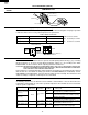
DOOR OPEN MECHANISM
1. The door release lever is pulled.
2. The upper latch head is lifted up by the linked door
release lever.
3. The latch lever is lifted up by the door release lever.
4. The joint lever is lifted up by the latch lever.
5. The lower latch head is lifted up by the joint lever.
6. Now both latch heads are lifted up, so they can be
released from the latch hook.
7. Now the door can be opened.
Latch head
Monitor switch (1)
Latch hook
Secondary interlock
switch (1)
Door sensing switch
Latch head
Joint lever
Door release
lever
Latch lever
Secondary interlock
switch (2)
Monitor switch (2)
Switch lever C
Switch lever A
Switch lever B
Figure D-1. Door Open Mechanism
DOOR SENSING SWITCH
The door sensing switch is activated by the latch head of the
door and switch lever C. When the door is opened, the
contacts of the switch open and interrupt the circuit to the
coils of the primary interlock relay (1), (2). The contacts of
the primary relay (1), (2) then open and interrupt the circuit
to the primary winding of the power transformers. At this
time, the contacts of relay RY1 close and the blower motor,
stirrer motors and oven lamps are energized for 1 minute.
SECONDARY INTERLOCK SWITCHES (1), (2)
The secondary interlock switch (1), (2) are activated by the
upper latch head of the door and switch lever B. When the
door is opened, the contacts of the switch open and interrupt
the circuit to the primary winding of the power transformers
(1), (2).
MONITOR SWITCHES (1), (2)
The monitor switches (1), (2) are mounted in the upper
position of the latch hook. The monitor switches are acti-
vated by the upper latch head of the door and switch lever
A. When the door is opened, the contacts of the monitor
switches close. Monitor switch (1) is intended to render the
oven inoperative by means of blowing the monitor fuse,
when the contacts of the primary interlock relay (1) and
secondary interlock switch (1) fail to open when the door is
opened. Monitor switch (2) is intended to render the oven
inoperative by means of blowing the monitor fuse, when the
contacts of the primary interlock relay (2) and secondary
interlock switch (2) fail to open when the door is opened.
Functions:
With the door shut, the contacts of the door sensing switch
and the secondary interlock switches (1), (2) are closed and
the contacts of the monitor switches (1), (2) are open.
1. When the door is opened, the contact of the door sensing
switch and secondary interlock switches (1), (2) are
opened first, then the contact of the monitor switches (1),
(2) are closed.
2. As the door goes to a closed position, the contacts of the
monitor switches (1), (2) are opened first, then the
contacts of the door sensing switch and the secondary
interlock switches (1), (2) close.
3. If the door is opened, and the contacts of the primary
interlock relay and secondary interlock switch of the
same circuit fail to open, the monitor fuse blows
simultaneously with closing of the monitor switch contacts
of that circuit (1 or 2).
CAUTION: BEFORE REPLACING A BLOWN MONITOR
FUSE TEST THE DOOR SENSING SWITCH,
PRIMARY INTERLOCK RELAYS (1), (2), SEC-
ONDARY INTERLOCK SWITCHES (1), (2) AND
MONITOR SWITCHES (1), (2) FOR PROPER
OPERATION. (REFER TO CHAPTER "TEST
PROCEDURE").
NOTE: MONITOR FUSE AND SWITCH ARE REPLACED
AS AN ASSEMBLY.
MAGNETRON THERMAL CUT-OUTS (1), (2)
The thermal cut-outs (1), (2) located on the top of the upper
and lower waveguide, are designed to prevent damage to
the magnetrons (1), (2). If an over heated condition devel-
ops in the tube due to blower motor failure, obstructed air
ducts, dirty or blocked air intake, etc., the circuit to the
magnetrons are interrupted. Under normal operation, the
thermal cut-outs remains closed. However, when abnor-
mally high temperatures are generated within the magnetron,
the thermal cut-out will open at 293˚F (145˚C) causing the
microwave energy to stop. The defective thermal cut-out
must be replaced with new rated one.
OVEN THERMAL CUT-OUT
The thermal cut-out, located on the side of the exhaust duct
assembly, is designed to prevent damage to the oven by
fire. If the food load is overcooked, by either error in cook
time or defect in the control unit, the thermal cut-out will
open. Under normal operation, the oven thermal cut-out
remains closed. However, when abnormally high tempera-
tures are generated within the oven cavity, the oven thermal
cut-out will open at 239˚F (115˚C), causing the oven to shut
down. The defective thermal cut-out must be replaced with
new rated one.
OVEN THERMISTOR
The thermistor is a negative temperature coefficient type.
The temperature in the exhaust duct is detected through the
resistance of the thermistor.
If the temperature is high, the control panel will display “EE7”
and the oven will stop to avoid overheating and catching fire.
If the thermistor is open, the control panel will display "EE6"
and the oven will stop.
DESCRIPTION AND FUNCTION OF COMPONENTS