
Specifications


April – June 2002 ExtroNews 13.2 15
TECHNICALLY SPEAKING...
number of cycles of carrier signal
corresponding to the burst period
representing the first part of a ONE or ZERO
may be of the same time interval with the
delineation between the two being the
number of carrier cycles for which no burst
is sent. The carrier burst ON time along with
the carrier burst OFF time is called a
“burst pair.”
Data bit timing is determined by taking
the reciprocal of the carrier frequency and
multiplying by the prescribed number of
carrier cycles for which we wish to have
represent a data bit. For example, the
reciprocal of 38 kHz is about 26.3
microseconds (one carrier cycle). In one of
the most popular IR remote protocols, a
ONE is represented by 22 cycles of carrier
ON followed by 96 cycles of carrier OFF. So,
a logical ONE burst pair timing ratio is 22,
96. The zero burst pair is communicated by
22, 24. Therefore, the time to communicate
a ONE is (22+96) x 26.3 µS = 3.1 mS and
the time to send a ZERO is (22+24) x 26.3
µS = 1.2 mS.
Now, creating an actual transmission
involves more than just sending the data.
Most IR transmissions utilize a “start” pulse
period to “wake up” the IR receivers and
provide them the time to adjust to the
incoming signal strength via their automatic
gain control (AGC) circuit. Demodulation is
optimized by setup of the system gain and
this, in large part, is responsible for the
system’s noise immunity. In our example,
the start pulse burst pair is 341, 171 which
is a fairly long time interval, about 9 ms
followed by 4.5 ms dead time. Following
this start pulse are the data bits starting
with the least significant bit (LSB) first. After
all data bits are sent, there is a “stop” pulse
burst pair of 22, 1427 which signifies the
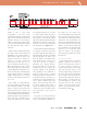
end of transmission. See Figure 3 above.
In this example, the full data transmission
is constructed of four bytes. The first and
second bytes signify the device address. The
third byte identifies the function command
and the fourth byte is the inverse of the
third. The addition of the third with the
fourth should equal 255. If this does not
occur when the data is decoded, a
transmission error is detected. Therefore,
the entire transmission is 34 burst pairs
including start, data, and stop bits. The
total time required for the transmission
varies depending on the complement of
data ones and zeros. There is a nominal
40 ms rest period between transmissions. If
a particular function key, say volume up, is
continuously pressed, the transmitter may
send a repeat command about every
180 mS. The receiver decides when to use
the repeat command. Battery power is
saved in the transmitter by using a repeat
command code and not sending an entire
code string when a key is held for
long periods.
The receiver “sees” the carrier burst and,
since we know that radio signal detectors
convert a carrier without modulation to a
DC voltage level, the output of the
receiver’s demodulator provides a high level
when the carrier is detected and returns to
low level when no carrier is detected. This is
simple burst carrier demodulation. The
microprocessor that ultimately must make
sense of all the data bits looks for the large
difference in data periods represented by
the one and the zero. The fact that the time
interval for a one is several times longer
than a zero makes for easy recognition.
Once detected, the data bits are processed
like other data.
Long Live The Clicker
It seems wherever there is an electronic
appliance today, there’s an IR remote to
operate it. How many remote controls do
you own? IR control has become an
essential commodity. And, even if we really
don’t need the remote control for every
electronic gadget we buy, we think we do.
Let’s face it, IR remotes have changed the
way we interface with electronic devices.
The functionality expands and continues to
improve. Imagine – now that we have low
cost sound synthesis too, maybe we could
incorporate that into these IR remote
systems to re-create “the clicker” and the
sound of that old motorized RF tuner…
how technically nostalgic.
Figure 3. An example of an IR data transmission and its construction.