Dear SHARP Customer IMPORTANT For your assistance in reporting the loss or theft of your Color LCD Projector, please record the Serial Number located on the rear of the projector and retain this information. Model No.: PG-D100U Serial No.: Important Information There are two important reasons for prompt warranty registration of your new SHARP LCD Projector, using the REGISTRATION CARD packed with the projector.
WARNING: FCC Regulations state that any unauthorized changes or modifications to this equipment not expressly approved by the manufacturer could void the user’s authority to operate this equipment. U.S.A. ONLY INFORMATION This equipment has been tested and found to comply with the limits for a Class A digital device, pursuant to Part 15 of the FCC Rules. These limits are designed to provide reasonable protection against harmful interference when the equipment is operated in a commercial environment.
IMPORTANT SAFEGUARDS 14) Lightning – For added protection for this product during a lightning storm, or when it is left unattended and unused for long periods of time, unplug it from the wall outlet and disconnect the cable system. This will prevent damage to the product due to lightning and power-line surges. 15) Overloading – Do not overload wall outlets, extension cords, or integral convenience receptacles as this can result in a risk of fire or electric shock.
Cautions Concerning the Laser Pointer AVOID EXPOSURE-LASER RADIATION IS EMITTED FROM THIS APERTURE. CAUTION - use of controls or adjustments or performance of procedures other than those specified herein may result in hazardous radiation exposure. LASER LIGHT WINDOW CAUTION LASER RADIATIONDO NOT STARE INTO BEAM WAVE LENGTH : 670nm MAX. OUTPUT : 1mW CLASS II LASER PRODUCT "COMPLIES WITH 21 CFR SUBCHAPTER J" SHARP ELECTRONICS CORPORATION SHARP PLAZA, MAHWAH, NEW JERSEY 07430 U.S.A.
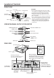
Location of Controls FRONT VIEW Remote sensor Focus knob Zoom knob CAUTIONS: • Do not touch the lamp, lamp cage cover, cooling fun, and their surrounding areas while the projector is on. They are very hot and may cause burns. • Allow at least 4" (10 cm) of space between the cooling fan (exhaust vent) and the other nearest wall or obstruction. • If the cooling fan becomes obstructed, a protection device will automatically turn off the projector lamp.
Operating the Wireless Mouse Remote Control The functions of your personal computer’s mouse have been built into the remote control enabling you to operate your projector and personal computer with only the remote control. 1. Slide the main power switch on the side of the unit on. 2. Press the POWER ON button on the front panel of the remote control to turn the projector power on. 3. When using the remote control as a wireless mouse, move the MOUSE/ADJUSTMENT sliding switch to the MOUSE position.
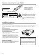
Using the optional cable with the remote control • When the remote control cannot be used due to the range or positioning of the projector (rear projection, etc.), connect the optional cable from the Wired Remote Control Jack of the remote control to the Wired Remote Input on the back of the projector. TOP VIEW REMOTE CONTROL SIGNAL TRANSMITTER Note: • The signal transmitter does not function when the optional cable is connected to the remote control. WIRED REMOTE CONTROL INPUT (3.
Wireless Mouse Functions By attaching the provided mouse cable to both the mouse terminal on your projector and the mouse terminal on your personal computer, you can use the wireless mouse built into the remote control, instead of the mouse equipped with your personal computer, to operate your personal computer. The wireless mouse functions will work with personal computers compatible with IBM PS/2, serial (RS-232C) or Apple ADB type mouse systems.
Setting Up the Projector Using the Focus and Zoom • Zoom, Focus and Reversed/Inverted Image mode functions broaden your options for projector placement. • See pages 11 and 12 for details on projector setup. SIDE VIEW Zoom Ceiling setting Invert Image Table setting Zoom 1. Turn on the MAIN POWER. Turn on the main power switch. 2 2. Turn on the POWER POWER POWER indicator Press the POWER ON/OFF button on the projector or remote control to turn on the power. LAMP TEMP. 3 3.
Projector Distance and Picture Size Relationship ■ The zoom lens allows adjustment of the image size within the projector’s range. ■ For optimum picture adjustment, the projector should be placed and adjusted at a distance between 5.1 ft to 56.3 ft from the screen. Distance from screen Picture size (diag.) 300 inches 150 inches 100 inches 80 inches 60 Inches 40 inches Picture size: 100 inches (254 cm) Projection distance (L) Maximum projection distance Minimum projection distance 40.0 ft (12.2 m) 56.
Using the Image Invert/Reverse Function ■ This projector is equipped with an image invert/reverse function. The projected image can be inverted or reversed by using the MENU button and the ADJUSTMENT / and / buttons. 1 1. Press the MENU button. IMAGE ADJ. BLACK SCREEN INPUT DISPLAY E-ZOOM REVERSE INVERT :SEL. :ADJ. [OFF] [OFF] [OFF] [OFF] [OFF] MENU : E N D 2 2. Reversed Image Mode .
Example of a standard setup TOP VIEW SIDE VIEW Lens center 90° → → 90° Lens center If the projector and screen are not centered properly, the picture will be distorted, making viewing difficult. The projector lens should be centered in the middle of the screen. ■Using the horizontal reverse function makes the following setups possible.
Adjusting the Height of the Picture Use the adjuster release to adjust the angle of the projector and height of the picture. Minor adjustments can be made with the adjusters. Adjuster release Adjusters 1. Press the adjuster release and lift the projector to the desired angle with both hands. 1 • The adjuster legs will extend to the surface of the table. 2 2. Remove your hand from the adjuster release. • The adjuster legs will lock in position.
Connecting the Projector Input terminals This section explains how to connect the projector to audio/video equipment such as a VCR, Laser Disc, or external audio amplifier. Always turn off the LCD Projector while connecting to video equipment, in order to protect both the projector and the equipment being connected. • Press on the portion labeled PUSH and open the cover to make the necessary connections.
Connecting the Projector (RGB: Computer) • Please carefully read the manual of the computer you will be connecting. • Before connecting, be sure to turn both the projector and the computer off. After making all connections, turn the projector on first. The computer should always be turned on last. • Press on the portion labeled PUSH and open the cover to make the necessary connections.
Connecting to the Computer RGB Input/Output Terminals You can connect your projector to a computer for easy projection of full-color computer images, and an external monitor for simultaneous viewing. 1 Side view of the projector COMPUTER RGB IN RGB Signal Input Socket OUT 1.
3. Connecting to other compatible computers When connecting the projector to a compatible computer other than an IBM-PC (VGA/SVGA/XGA) or Macintosh series, a separate cable is needed. Please contact your dealer for ordering information. Notes: • Connecting computers other than the recommended types may result in damage to the projector, the computer, or both. • Connect the audio from the computer to the COMPUTER AUDIO INPUT terminal. 4 MOUSE OUT FOR PC98 AUDIO L OUT R WIRED REMOTE 4.
Input Signals (Recommended Timing) For IBM and compatibles For Apple Macintosh Series Input signals: The video output signal timing of different types of video signals are shown below for reference.
RGB Adjustment Controls When displaying computer patterns which repeat every other dot (tiling, vertical stripes, etc.), interference may occur between the LCD pixels, causing flickering, vertical stripes, or contrast irregularities in portions of the screen. Should this occur, use the ADJUSTMENT / buttons for HORIZONTAL (LEFT/RIGHT) and VERTICAL (UP/ DOWN) POSITION ADJUSTMENTS to adjust for the optimum picture. RGB INPUT ADJUSTMENTS (CLOCK, PHASE, V-POS and H-POS) 1.
Basic Operation of the Projector 1 1. Connect the AC cord OFF ON 2 MAIN POWER switch 1 Open the socket cover and connect the supplied AC cord to the socket. AC cord 2 2. Turn on the MAIN POWER POWER OFF ON When the MAIN POWER is on, the POWER indicator lights red. LAMP Turn the MAIN POWER switch on the side of the projector. The POWER indicator lights red and the projector enters STANDBY mode. TEMP. 3 Projector ON/OFF Remote control ON/OFF ON OFF POWER LAMP TEMP.
On-Screen Display 5. Select one of eight ON-SCREEN DISPLAY languages LANGUAGE You can return to the previous screen by selecting the uppermost item (turquoise) with the ADJUSTMENT / buttons (in this case, LANGUAGE) and then pressing the ENTER button. ENGLISH DEUTSCH ESPAÑOL NEDERLANDS FRANÇAIS ITALIANO SVENSKA :SEL. The on-screen display is set to English at the factory. The language for the unit’s ON-SCREEN DISPLAY can be set to English, German, Spanish, Dutch, Swedish, Italian, French or Japanese.
7. Select input On-Screen Display VIDEO •N T S C RGB For viewing the picture from a video source connected to: VIDEO INPUT or S-VIDEO INPUT COMPUTER RGB 1024×768 60 Hz Mac RGB RGB 1024×768 60 Hz 800×600 60 Hz RGB RGB RGB 640×480 35 KHz 640×480 34.97 KHz 832×624 Press the INPUT SELECT button to switch the picture input. When you press the button, the current input mode is displayed for about 4 seconds.
Adjusting the Picture • This projector’s picture is factory preset to standard settings. However, you can adjust it to suit your own preferences with the ADJUSTMENT buttons on the projector and the remote control. • The adjustments can be memorized in RGB or VIDEO separately. • Four picture modes can be adjusted: “PICTURE,” “BRIGHT,” “RED,” and “BLUE.” Adjusting the Picture 1 1. Use the MENU button to select the mode to be adjusted.
Computer Mode Memory Adjustments • The projector has been preset with different modes for use with SVGA and other compatible computers. However, 7 memory positions are provided to store mode adjustments. • Each memory position can be used to store mode adjustments to match the computer. 1. Press the ENTER button to select the Memory Adjustment mode. 1 When RGB is selected. RGB RGB ADJ. RGB INPUT ADJ. IMAGE ADJ. AUDIO SYSTEM SETUP LANGUAGE :SEL. ADJ.
Adjusting the Audio • The projector’s audio is factory preset to the standard setting. However, you can adjust it to suit your own preference with the ADJUSTMENT buttons on the projector or the remote control. • You can adjust the BALANCE, TREBLE and BASS, and also select the SRS 3-D SOUND mode. • To return to the factory preset mode, press the ADJUSTMENT / buttons to select RESET, then press the ENTER button. • Press the MENU button to select the normal screen mode.
E-ZOOM Function E-ZOOM Function ■ This projector has an E-ZOOM (640 × 480 dot, etc.) mode which enlarges the display when inputting an image of less than 800 × 600 dot in resolution. In the XGA (1024 × 768 dot) mode, compression enables full-mode display. 1 On-Screen Display IMAGE ADJ. BLACK SCREEN INPUT DISPLAY E-ZOOM REVERSE INVERT :SEL. :ADJ. [OFF] [OFF] [ON] [OFF] [OFF] 1. Press the MENU button to select E-ZOOM mode. Press the MENU button.
Functions on the Projector Setting Up the System • Using this function, you can check the input signal and select the remote mouse. Checking the system On-Screen Display SYSTEM • Press the MENU button. Select SYSTEM SETUP with the ADJUSTMENT / buttons. Then press the ENTER button to change to the picture indicated on the left. • The current system conditions will be displayed on the screen. • Press the MENU button to select the normal screen mode. SETUP 800×600 3 7 .
On-Screen Display IMAGE ADJ. BLACK SCREEN INPUT DISPLAY E-ZOOM REVERSE INVERT :SEL. :ADJ. [ON] [OFF] [OFF] [OFF] [OFF] MENU : E N D LCD Projector Using the Black Screen Function This projector is equipped with a Black Screen Function. This function can be used to black out the presentation image. • Press the MENU button. While the MENU screen is displayed, press the ADJUSTEMENT / buttons to select IMAGE ADJ. Then press the ENTER button to display the IMAGE ADJ. screen shown.
On-screen Display IMAGE ADJ. BLUE SCREEN BLACK SCREEN INPUT DISPLAY SYSTEM REVERSE INVERT :SEL. :ADJ. [ON] [OFF] [OFF] [OFF] [OFF] MENU : E N D On-screen Display REMAIN 5M REMAIN 4M Using the Blue Screen Function This projector is equipped with a Blue Screen function that will turn the screen blue when the video input terminal is not connected to anything, or the video component is turned off. • Press the MENU button.
Air Filter Maintenance ■ The air filter should be cleaned every 100 hours of use. Clean the filter more often when the projector is used in a dusty or smoky location. ■ Have your nearest Authorized Sharp Industrial LCD Products Dealer or Service Center replace the filter (PFILD 0051CEZZ) when it is no longer possible to clean it. AIR FILTER cover Cleaning and Replacing the Filter 1 Turn OFF the MAIN POWER. 2 Remove the FILTER COVER. Press the arrow mark on the air filter cover and pull straight out.
Lamp/Maintenance Indicators Lamp ■ The Lamp has a finite operating life. The lamp for this projector has a usable life of 2000 cumulative hours. This number may differ, however, depending on the ambient conditions. 1. When the lamp is nearing the end of its operating life, the picture and color quality will deteriorate.
Lamp Replacement The lamp in the projector has a finite service life. The lamp for this projector has a usable life of 2000 cumulative hours. This number may differ, however, depending on the ambient conditions. The lamp requires replacement in the situations given below. • When the picture starts becoming dark and the color contrast deteriorates.
Caution: Because some parts may not be sufficiently cooled, be sure to remove the lamp cage by the handle while taking care not to touch the metallic areas. Note: Do not allow anything to hit the UV filter (j). Installing the lamp unit 1. Hold lamp cage (h) by the handle (g) and press it in firmly while making sure that the lamp cage (h) properly connects to the connector (i). 2. Tighten screws (e), (f) and (d), then perform the above instructions in the reverse order. Resetting the lamp timer 1.
Connection Pin Assignments Analog RGB Signal Input and Output Terminal : 15-pin mini D-sub female connector Computer Input Analog 5 10 15 1 6 11 1. 2. 3. 4. 5. 6. 7. Video input (red) Video input (green) Video input (blue) Reserve input 1 Composite sync (Mac only) Earth (red) Earth (green) 8. Earth (blue) 9. GND 10. GND 11. GND 12. Reserve input 2 13. Horizontal sync signal 14. Vertical sync signal 15. Reserve input 3 Mouse Input Terminal (for IBM/Mac) : 9-pin D-sub female connector Pin No.
RS-232C Terminal Specifications 1. PC control The personal computer can control the projector by connecting the two via an RS-232C cable (not supplied). 2. Communication conditions Set the serial port settings of the computer to match that of the table below. Signal format: Conforms to RS-232C standard. Baud rate: 9600bps Data length: 8 bits Parity bit: NON Stop bit: 1 bit Flow control: None 3. Basic format Commands from the computer are sent in the following order: command, parameter, and return code.
RS-232C Terminal Specifications COMMAND CONTROL ITEM VOLUME ADJUSTMENT C1 C2 C3 PARAMETER C4 RGB INPUT ADJUSTMENT P2 P3 CONTROL CONTENTS P4 V O L A _ _ * * VOLUME (0 ~ 60) M U T E _ _ _ 0 MUTE OFF _ _ _ 1 MUTE ON A A B L _ * * * BALANCE (-30 ~ +30) A A T E _ * * * TREBLE (-30 ~ +30) A A B A _ * * * BASS (-30 ~ +30) S R S M AUDIO ADJUSTMENT RGB ADJUSTMENT P1 _ _ _ 0 SRS OFF _ _ _ 1 SRS MODE1 _ _ _ 2 SRS MODE2 _ _ _ 3 SRS M
Specifications Product Type Model Video system Display method LCD panel Lens Projection lamp Contrast ratio Video input signal S-video input signal Video output signal Horizontal resolution Audio output Computer RGB input signal RS-232C input terminal Mouse input terminal (for IBM/Mac) Mouse input terminal (for PC98) Speaker system Rated voltage Rated frequency Power consumption Operating temperature Storage temperature Cabinet Laser Pointer of Remote Control Dimensions (W × D × H) Weight Supplied accesso
Dimensions 21/64 (51) 15 9/32 (388) 11 29/64 (291) Top View 10 25/64 (264) /64 (10) ø2 43/64 (ø68) 2 29/32 (74) 25 149/64 (45) Front View 8 27/64 (214) Bottom View E-38 4 23/32 (120) Side View [Units: inches (mm)]