
Service manual


LC-20B1U
9
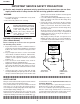
REMOVING OF MAJOR PARTS
1. Remove the two back covers.
2. Remove the table stand fixing screws (4 pcs.).
3. Rear cabinet is detached opening some rear cabinet and shifting to a PC card slot side,
where a card release button is pushed in.
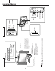
4. Remove the reinforcement angle fixing screws (4 pcs.).
5. Remove the PC card unit.
5-1. Detach the connector.
5-2. Remove the PC card frame angle
fixing screws (2 pcs.).
5-3. Remove the ground cable
fixing screws (3 pcs.).
6. Detach the connector from each PWB.
5-2
PC Card Frame Angle
When you attach FFC, a
black dot mark should be
on a card unit side.
[CAUTION]
PC CARD Unit
5-3
5-2
5-3
5-3
5-1
ANALOG PWB
INVERTER-A
PWB
INVERTER-B PWB
DIGITAL PWB
RC/LED PWB
CONTROL PWB
4
Reinforcement Angle
6
6
66
6
6
6
6
6
6
6
6
6
6
6
6
6
6
6
6
6
6
V
O
LC
H
M
E
N
U
T
V
/
V
I
D
E
O
M
A
I
N
P
O
W
E
R
Front Cabinet
Rear Cabinet
Table Stand
Back Cover
Back Cover
1
1
2
3
3
3
3
3
3