POS TERMINAL MODEL ER-A770 INTER-REGISTER COMMUNICATION SYSTEM INSTRUCTION MANUAL
TABLE OF CONTENTS Page Introduction ............................................................................................................................... 3 Inline Operation ........................................................................................................................ 4 1. Message display ................................................................................................................ 4 (1) The message displayed during inline communications..................
7. Downloading the contents of the IRC programming to satellites — master .................... 35 (1) Initial downloading ...................................................................................................... 35 (2) Maintenance downloading .......................................................................................... 36 8. Programming for the remote printer .................................................................................
Introduction The ER-A770 inter-register communication (IRC) system consists of one master machine and up to 15 satellite machines/remote printers (max. 9 remote printers) which are all interconnected by the Sharp Retail Network (SRN) to provide data transmission among them. This system allows the manager to exercise centralized control over the satellites through the master. Sharp Retail Network Master Satellite Satellite Remote Printer (max. 9 remote printers) Max.
1 Inline Operation 1. Message display (1) The message displayed during inline communications 1) The message shown at below is displayed at the master engaged in IRC transmission (when the broadcasting method has been preset). ex.: SENDING DATA NOTE The above message is also displayed at the satellite which is engaged in system resetting transmission. 2) The machine number of the satellite that is communicating with the master is instantaneously displayed at the master after IRC transmission.
(2) Error messages When an error occurs, a corresponding error message is displayed. For a description of the error messages, see the “List of error messages” below. List of error messages Error message (Default) Description BUSY • The target machine is busy. LACKING MEMORY • The GLU, drive-through code, or related file memory is full. MOTOR LOCK • The remote printer head did not operate correctly. NO AUTHORITY • The server who entered a GLU/PBLU code was not authorized.
2. Open store operation (PGM2 mode) — master and satellite When the open store operation is performed at the master, the IRC system is opened and the registration function becomes available at all the machines in the IRC system.
3. Close store operation (PGM2 mode) — master and satellite When the close store operation is performed at the master, the inline system is closed and the registration function becomes unavailable at all the machines in the inline system. It should be noted that for the close store operation, all the satellites must be in their SIGN-OFF state. After this operation, the communications between the master and satellites which have been enabled with the open store operation are disabled.
4. Sign-on operation (server assignment) (REG mode/MGR mode) The sign-on operation is intended to assign a server to a machine (satellite or the master) and enable him or her to perform entry operations at the machine. If a server successfully signs on at a machine, his or her server name appears on the LCD of the machine. The server memory is under the control of the master. The sign-on operation can be done whether the machine is in the open store or close store state.
5. Server sign-on report A server sign-on report can be generated at the master. This report is used to determine at which terminal each server has signed on. Report generation procedure 1. Select “PGM2 MODE” from the mode selection menu and press the [ENTER] key. 2. Select “INLINE READING” from the PGM2 MODE menu and press the [ENTER] key. 3. Select “SIGN ON SERVER” from the INLINE READING menu and press the [ENTER] key. 4. Select “DISPLAY” or “REPORT PRINTER” and press the [ENTER] key.
6. Sign-off operation (cancellation of server assignment) (REG mode/MGR mode) The sign-off operation is intended to cancel the assignment of a server to a machine. The sign-off operation at a machine (master or satellite) can be done only for the servers who have signed on at the machine and are not in the middle of a registration entry. Sign-off procedure Keyboard entry sequence (REG/MGR/X1/Z1/X2/Z2/PGM1/PGM2 modes) [SERV#] NOTE • The sign-off operation only applies to the server who has signed on.
7. Look-up and updating of the GLU/PBLU file In the IRC system, the following two types of GLU/PBLU file allocation system are available: a centralized system and an individual system. (1) Centralized GLU/PBLU file system In this system, the GLU/PBLU file exists only in the master. All satellites in the IRC system can access the GLU/PBLU file in the master for registration.
8. Drive-through function Depending on the setup of your system, drive-through data is either centrally controlled by the master or Individually looked up at each terminal. For more information, please contact your authorized SHARP dealer. Automatic code generation Drive-through codes are generated automatically: when the end code for a transaction is generated, the start code for another transaction is automatically generated.
NOTE The drive-through system provides three types of the terminal operations (Order Taker Machine/Cashier Station Machine/Counter Machine). For more details about the system configuration, please consult your authorized SHARP dealer.
9. T-LOG polling All REG-mode transaction data in each satellite is saved in its T-LOG buffer. T-LOG polling is a data collecting system in which the master collects data from the T-LOG buffers in satellites. T-LOG polling becomes available upon open-store operation and becomes unavailable upon close store operation. A request for T-LOG polling is issued from the satellite to the master when the number of data records in its T-LOG buffer exceeds a predetermined number in the open store state.
10. Communication with a remote printer (option) When a remote printer is included in the inline system, order data is output to the remote printer according to preset data on the remote printer. The remote printer is used to print all or part of the data entered at a machine. It is also called a kitchen printer. It can also be operated at a location other than the kitchen.
(2) Remote printer send function This function allows partial food orders to be sent to the remote printers. Which printer to receive the order is selectable. The function is intended to allow the cooking staff to begin preparing certain items before the entire order is given. *Case 1) (Item entry) NK **Case 2) NK: 1-9 SEND ORDER *Case 1) A partial food order is sent to one or several remote printers which has been specified by the department/PLU programming.
11. Rerouting receipt/journal print data In restaurant environments, terminals may or may not need a receipt/journal printer. One external printer connected by RS-232 cable can be shared by two or more ER-A770 machines.
2 Consolidated and Individual Reports The system can generate two types of sales reports: consolidated reports (reports on all or specified machines in the system) and individual reports (reports on an individual machine). At the master, you can generate consolidated reports on all or specified satellites and reports on the master itself. At each satellite, you can generate certain reports on the satellite. 1. Operating modes X1 mode: Z1 mode: X2 mode: Z2 mode: OP XZ mode: Daily sales reading reports.
3. Consolidated reports — master/back-up master (1) Report generation procedure To generate respective reports, use the following procedure, referring to the list of consolidated reports on the following pages. 1. Select the required operating mode (OP XZ, X1, Z1, X2, or Z2) from the mode selection menu and press the [ENTER] key. 2. Select SYSTEM and press the [ENTER] key. 3. Select the type of report you wish to generate and press the [ENTER] key.
(2) List of consolidated reports (SYSTEM READING/RESETTING) These reports can be printed on the printer unit (option) or shown on the display screen. Operating modes Report type DEPARTMENT Description OP XZ X1 Z1 X2 Z2 Job # Required data/Remarks Full department report 1110 Individual dept. group report 1112 DEPT. GROUP TOTAL Dept. group total report 1113 M-DOWN FOR DEPT. Department markdown report 1119 PLU PLU report by specified range 1120 PLU BY DEPT PLU report by associated dept.
Operating modes Report type Description OP XZ X1 Z1 X2 Z2 Job # CID Cash-in-drawer report 1131 TAX Tax report 1133 Required data/Remarks For all servers 1233 ALL SERVER Full server report 1140 1240 IND. SERVER Individual server report 1041 1141 1241 ALL MANAGER IND. MANAGER EMPLOYEE Full manager report 1148 Individual manager report 1149 Employee report 1155 specified range 1248 Manager no. 1249 1255 Employee code. (The range can be specified by entering start and end codes.
Operating modes Report type OP XZ X1 Z1 X2 Z2 Job # Required data/Remarks DAILY NET Daily net report 1270 INGREDIENT STOCK Ingredient stock report 1175 Ingredient table no. GLU GLU report 1180 GLU/PBLU code. (The range can be specified by entering start and end codes.
4. Individual reports — master/back-up master/satellite (1) Report generation procedure To generate respective reports, use the following procedure, referring to the list of individual reports on the following pages. 1. Select the required operating mode (OP XZ, X1, Z1, X2 or Z2) from the mode selection menu and press the [ENTER] key. 2. Select INDIVIDUAL and press the [ENTER] key. 3. Select the type of report you wish to generate and press the [ENTER] key.
(2) List of individual reports (READING/RESETTING) These reports can be printed on the printer unit (option) or shown on the display screen. Operating modes Report type DEPARTMENT Description OP XZ X1 Z1 X2 Z2 Job # Full department report 110 Individual dept. group report 112 DEPT. GROUP TOTAL Dept. group total report 113 M-DOWN FOR DEPT. Department markdown report 119 PLU PLU report by specified range 120 DEPT. IND. GROUP PLU BY DEPT PLU IND.
Operating modes Report type TAX Description Tax report OP XZ X1 Z1 X2 Z2 Job # Required data/ Remarks 133 MA, SL 233 ALL MANAGER IND. MANAGER HOURLY Full manager report 148 Individual manager report 149 Hourly report Notes* MA, SL 248 Manager no. MA, SL 160 For an individual time range MA, SL 160 For all 48 half-hours with zero skipped MA, SL 249 DAILY NET Daily net report 270 MA, SL INGREDIENT STOCK Ingredient stock report 175 Ingredient table no.
5. Server report At the master, you can generate consolidated transaction reports on all servers or individual servers by reading or resetting operation. At each satellite, you can generate consolidated transaction reports on individual servers by reading or resetting operation. If a specific server is signed on at a machine when resetting operation for a consolidated individual server report is made at the machine, the data on transactions being handled by the server is also added and printed out.
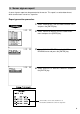
3 IRC Programming First, turn on the machines in the IRC system and place them in the PGM2 mode. The programming procedures for both the master and satellites will be explained below. 1. Setting the machine numbers — master and satellite It is necessary to insure that each terminal has an assigned machine number to the master and satellites prior to further IRC programming. 1. Select “PGM2 MODE” from the mode selection menu and press the [ENTER] key to enter the PGM2 mode. 2.
2. Setting the terminal numbers (IRC machine numbers) — master and satellite It is assumed that your terminal’s setting for inline operations has been performed. 1. Enter the PGM2 mode. 2. Select “INLINE SETTING” and press the [ENTER] key. 3. Enter a terminal number (0 - 254) and press the [ENTER] key. (For programming for BMA MACHINE No. and SYSTEM RETRY, see pages 31 - 32.) 4. Repeat steps 1 to 3 for all machines in the IRC system.
3. Creating/updating the master list — master (1) Creating the master list (subwindow program) This may only be performed on the pre-designated master. 1. Enter the PGM2 mode. 2. Select “INLINE SETTING” and press the [ENTER] key. 3. Enter a terminal number (0 - 254) for the master and then carry out the programming for other INLINE SETTING items and press the [ENTER] key. The subwindow for the creation of the master list will open. (For programming for BMA MACHINE No. and SYSTEM RETRY, see pages 31 - 32.
NOTE • The terminal numbers and machine numbers of the master and satellites must be entered into the master list for IRC communications. • The terminal numbers and machine numbers of up to 16 machines (one master and 15 satellites) can be entered into the master list. • The terminal number should be within the range from 1 to 254 and the machine number from 1 to 999999. • A satellite can not perform inline communications unless its terminal and machine numbers are present in the master list.
4. Specifying whether to enable or disable the system retry function when a transmission error occurs — master and satellite You can specify whether the system retry function is disabled or enabled if the communication between machines does not end successfully. 1. Enter the PGM2 mode. 2. Select “INLINE SETTING” and press the [ENTER] key. The INLINE SETTING menu will open. 3. Move the cursor to the “SYSTEM ENTRY” line. Select “DISABLE” or “ENABLE” with the [ • ] key (toggle key) and press the [ENTER] key.
5. Specifying the terminal to serve as a back-up master — master You can assign one satellite to the function of a back-up master. If the master fails during guest check operation, the assigned terminal will perform the master’s function. A machine number within the range from 1 to 999999 can be entered. If zero is entered, there will be no back-up master in the IRC system. This job can be done in the INLINE SETTING window of the master. The default setting is 0 (no back-up master). 1. Enter the PGM2 mode.
6. Reading the contents of the IRC programming — master and satellite 1. Enter the PGM2 mode. 2. Select “INLINE READING” and press the [ENTER] key. The INLINE READING menu will open. 3. Select “INLINE PRESET” and press the [ENTER] key. 4. Select “DISPLAY” or “REPORT PRINTER” and press the [ENTER] key.
Terminal number of the satellite Terminal number of the master System retry function (enable/disable) List of the machines involved in the IRC system (terminal no./machine no.) System retry function (enable/disable) Back-up master (terminal no./machine no.) • You can also read the same contents of the IRC Programming on the display screen.
7. Downloading the contents of the IRC programming to satellites — master When you have completed or changed the IRC programming, distribute the IRC preset data from the master to all satellites in the IRC system. (1) Initial downloading For initial setup of the IRC system, use this downloading method. The preset data in the master is downloaded to each satellite, when the existing preset data in the satellite is cleared. 1. Enter the PGM2 mode. 2. Select “INITIAL D/L” and press the [ENTER] key.
(2) Maintenance downloading To update preset data for the IRC system, use this downloading method. The preset data in the master is downloaded to each satellite without clearing the existing preset data or totalizers. 1. Enter the PGM2 mode. 2. Select “MAINTENANCE D/L” and press the [ENTER] key. The MAINTENANCE D/L menu will open. 3. Select a preset data item for maintenance and press the [ENTER] key. If needed, enter the code range. 4.
List of downloading jobs (PGM2 mode) Menu Job # Item Description Note INITIAL D/L 4100 DEPT Department preset data Preset data copying with clearing 4119 DIRECT KEY MAINTENANCE D/L NOTE 4200 4218 4220 4222 4223 4225 4226 4227 4228 4232 4300 4409 4450 4600 Dept./PLU key preset data for direct depts.
8. Programming for the remote printer For connection of remote printers to the SRN, be sure to contact your dealer. (1) Assigning kitchen printer numbers to remote printers — master and satellite With the following procedure, you can do programming for the remote printers connected to the SRN. For initial setup of remote printers, please contact your authorized SHARP dealer. 1. Enter the PGM2 mode. 2. Select “KP SETTING” and press the [ENTER] key. The KP SETTING menu will open. 3.
(2) Assigning the second kitchen printer number to each remote printer — master and satellite With the following procedure, you can assign a second remote printer to which data should be output when the first remote printer encounters an error during transmission of that data. This assignment is made to prepare for remote printer disconnection due to printer breakdown or other troubles. After the KP SETTING menu appears, proceed as follows: 1.
(4) Specifying whether to enable or disable the function for data transmission to the remote printer — master and satellite If a remote printer is disconnected from the IRC system or any other problem occurs in it, you can disable your machine to stop data transmission to the remote printer. This prevents any error message from appearing on the machine display each time an entry to be transmitted to that printer is made.
(6) Specifying the format of chit printing — master and satellite If so desired, each PLU/department item may be preset to output to the receipt printer in a chit format. With the following procedure, you can specify what items to be printed on chits. 1. After programming for the KP PRESET items, press the [ENTER] key. 2. Move the cursor to the following CHIT FORMAT items and select PRINT or SKIP with the [ • ] key (toggle key).
9. Reading the contents of the remote printer programming — master and satellite 1. Enter the PGM2 mode. 2. Select “KP READING” and press the [ENTER] key. 3. Select “DISPLAY” or “REPORT PRINTER” and press the [ENTER] key. KP no. K.P name Data transmission: OK/NO Second KP no. KP.
10. Downloading the contents of the remote printer programming to satellites — master When you have completed the remote printer programming, you can distribute the preset data from the master to all satellites in the IRC system. 1. Enter the PGM2 mode. 2. Select “INITIAL D/L” and press the [ENTER] key. 3. The INITIAL D/L menu will open. Select “KP PRESET” and press the [ENTER] key. 4. If you wish to download the KP PRESET data to all satellites, select “ALL” and press the [ENTER] key.
11. Programming for the Manager Work Station (MWS) — master and satellite The SRN interface for the ER-A770 POS enables the ER-A770 to perform in-line communications to a host P.C. through the connection to a Manager Work Station (MWS).
(2) Programming of the time-out time The time-out value for receiving the data can be specified by the following procedure: 1. Enter the PGM2 mode. 2. Select “MWS SETTING” and press the [ENTER] key. The MWS SETTING window will appear. 3. Enter the time-out time (1 - 255 (sec)) and press the [ENTER] key. NOTE: This value will depend upon the application. Please consult your authorized SHARP dealer.
12. Reading the contents of the Manager Work Station (MWS) programming — master and satellite 1. Enter the PGM2 mode. 2. Select “MWS READING” and press the [ENTER] key. 3. Select “DISPLAY” or “REPORT PRINTER” and press the [ENTER] key. Terminal No.
4 System Back-Up 1. How the IRC back-up system works The IRC system incorporates a back-up system. One of the satellites can be designated to serve as a back-up master. When both the master and back-up master are in order, the system works in the following sequence: (1) Each satellite sends updated GLU/PBLU data to the master. (2) The master receives the data, processes it and sends it back to the satellite. (3) The satellite sends the updated data to the back-up master.
2. Master declaration — when the master or back-up master breaks down When the master or back-up master breaks down, the master declaration procedure should be taken to inform satellites of the breakdown. (1) When the master breaks down — Master declaration at the back-up master 1) A satellite detects a breakdown of the master through the system retry function when it is sending updated GLU/PBLU data to the master. At this point, the message “NO REPLY/ MASTER” appears in the pop-up window of the display.
The master declaration procedure is as follows: 1. Select “PGM2 MODE” from the mode selection menu and press the [ENTER] key. 2. Select “DECLARATION” and press the [ENTER] key. 3. Select “MASTER DECLARE” and press the [ENTER] key.
(2) When the back-up master breaks down — Master declaration at the master 1) A satellite detects a breakdown of the back-up master through the system retry function when it is sending updated GLU/PBLU data to both the master and back-up master. At this point, the message “NO REPLY/BACKUP” appears in the pop-up window of the display. NO REPLY/BACKUP 2) The master declaration operation must be done at the master.
3. Recovery declaration — when the master or back-up master recovers from a breakdown When the master or back-up master recovers from a breakdown, the recovery declaration operation should be taken to inform satellites of the recovery. (1) When the master recovers from a breakdown — Recovery declaration at the back-up master 1) The recovery declaration operation is done at the back-up master. 2) Each satellite stops sending updated GLU/PBLU data to the back-up master.
The recovery declaration procedure is as follows: 1. Select “PGM2 MODE” from the mode selection menu and press the [ENTER] key. 2. Select “DECLARATION” and press the [ENTER] key. 3. Select “RECOVER DECLARE” and press the [ENTER] key.
(2) When the back-up master recovers from a breakdown — Recovery declaration at the master 1) The recovery declaration operation is done at the master. 2) Each satellite stops sending updated GLU/PBLU data to the master temporarily. 3) The master sends the updated GLU/PBLU data files to the back-up master. 4) The master informs all satellites of the back-up master’s recovery. 5) The satellites restart sending updated GLU/PBLU data to the back-up master.
5 Error Recovery 1. Data clear operation With the data clear operation, you can clear various item memories when necessary. This operation should be done only when the master or system breaks down. (1) Data clearing of the electronic journal data — master and satellite You can clear the electronic journal data in the event of some trouble. This function is available at the master and satellites. Clearing procedure 1. Select “PGM2 MODE” from the mode selection menu and press the [ENTER] key. 2.
NOTE • For T-LOG polling, see page 14. • The above-mentioned data clearing jobs should be performed at the advice of your authorized SHARP dealer. (3) Data clearing of the transaction memory — master and satellite You can clear the transaction memory in the event of some trouble. This function is available at the master and satellites.
(6) Data clearing of the server sign-on state — master You can clear the server sign-on state in case of trouble. This operation is effective only for the sign-on flag for servers who are signed on at the master. Clearing procedure After selecting “DATA CLEAR” from the PGM2 MODE menu with the same procedure as steps 1 and 2 in “(1) Data clearing of the electronic journal data,” select “SIGN ON FLAG.
2. System retry function If a satellite terminates a transmission job unsuccessfully, the master either terminates the job immediately or awaits a command given through the keyboard, depending on whether the system retry function is disabled or enabled. When the system retry function is enabled, the master awaits the entry of a command and retries access depending on the command as explained below.
A) RETRY command (selection from the menu or press of the 1 key) B) ABORT command (selection from the menu or press of the 2 key) C) IGNORE command (selection from the menu or press of the 3 key) (* If there are only RETRY and IGNORE on the menu, press the 2 key.) A) RETRY command: When RETRY is selected, the master attempts a RETRY to the satellite; however, it does not retry when, due to the type of error (for example, command error), it is obvious that the RETRY will fail.
BASIC SPECIFICATIONS Transmission system: Serial synchronous, half-duplex transmission. Transmission line: Common bus system Transmission speed: 1 Mbits/sec Transmission distance: Total (main + branch) max. 1 km Transmission cable: Coaxial cable RG-58/U No. of connectable machines: Master: 1 Satellites/Remote printers: max. 15 (Remote printers alone: max.
6 Handling the Remote Printer • ER-03RP Physical characteristics Control panel Paper outlet Ribbon cover Online switch Line feed switch Paper cover SRN connector Power switch AC power receptacle 60
1. Lamps and switches (1) Lamps • Power lamp This lamp lights up when the power switch of the remote printer is turned on. • Online lamp This lamp lights up when the online switch is pressed, and goes off when the switch is pressed again. • Alarm lamp This lamp lights up when the remote printer malfunctions. In this case the printer neither prints any data nor feeds the paper.
2. Cut the paper along a straight line to remove the paper spool. 3. Press the line feed switch to remove the paper remaining in the printer. 3 to 5 cm 4. Fold the top end of the replacement paper roll by 3 to 5 cm securely as shown at left. How to fold paper 5. Insert the end of the folded paper deep into the paper chute of the printer and press the line feed switch to advance the paper. NOTE If paper is not inserted far enough, it will not advance when the line feed switch is pressed.
6. Remove the slack in the paper and set the roll in position. 7. Pass the top end of the paper through the paper cutter on the paper cover and close it. 3. Replacement of the ink ribbon cassette When the print becomes faint, replace the ink ribbon cassette with a new one according to the procedures described below. Be sure to turn off the remote printer before replacing the ink ribbon cassette. 1. Pull up the ribbon cover and remove it.
2. Rotate the take-up knob of the ink ribbon cassette in the direction of the arrow to tighten the ink ribbon. Ink ribbon cassette Take-up knob 3. Push the ink ribbon cassette to the left, then lift up its right side to remove it. 4. Rotate the take-up knob of the new ink ribbon Ink ribbon cassette to tighten the ink ribbon. Install the new ink ribbon cassette so that the ink ribbon sets into the gap between the dot head nose assembly and paper guide as shown at the left. 5. Close the ribbon cover.
• ER-04RP Physical characteristics Control panel Paper outlet Ribbon cover Online switch Line feed switch Paper cover SRN connector Power switch AC power receptacle 65
1. Lamps and switches (1) Lamps • Power lamp This lamp lights up when the power switch of the remote printer is turned on. • Online lamp This lamp lights up when the online switch is pressed, and goes off when the switch is pressed again. • Alarm lamp This lamp lights up when the remote printer malfunctions. In this case the printer neither prints any data nor feeds the paper.
2. Cut the paper along a straight line to remove the paper spool. 3. Press the line feed switch to remove the paper remaining in the printer. 3 to 5 cm 4. Fold the top end of the replacement paper roll by 3 to 5 cm securely as shown at left. How to fold paper 5. Insert the end of the folded paper deep into the paper chute of the printer and press the line feed switch to advance the paper. NOTE If paper is not inserted far enough, it will not advance when the line feed switch is pressed.
6. Take up the slack in the paper and set the roll in position. 7. Close the paper cover. 3. Replacement of the ink ribbon cassette When the print becomes faint, replace the ink ribbon cassette with a new one according to the procedures described below. Be sure to turn off the remote printer before replacing the ink ribbon cassette. 1. Remove the paper cover and the ribbon cover.
2. Pulling the release levers, lift up the auto cutter. 3. Rotate the take-up knob of the ink ribbon cassette in the direction of the arrow to tighten the ink ribbon. Ink ribbon cassette Take-up knob 4. Push the ink ribbon cassette to the left, then lift up its right side to remove it. 5. Rotate the take-up knob of the new ink ribbon Ink ribbon cassette to tighten the ink ribbon.
SHARP CORPORATION ERA770A_2IE10