
Service manual


LC-40/46/52/60LE810UN (1st Edition)
4 – 5
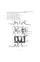
5. Removing of MAIN Unit, POWER/LED DRIVE Unit, Sub Woofer, Stand Angle Ass’y
1. Remove the 7 lock screws and detach the MAIN Unit
2. Remove the 2 lock screws and detach the TERMINAL Angle B .
3. Remove the 2 lock screws and detach the TERMINAL Angle S .
4. Remove the 6 lock screws and detach the POWER/LED DRIVER Unit .
5. Remove the 4 lock screws and detach the Sub Woofer .
6. Remove the 8 lock screws and detach the 2 VESA Angle .
7. Remove the 1 lock screw and detach the LCD Fixing Metal Angle B-L .
8. Remove the 1 lock screw and detach the LCD Fixing Metal Angle T-R .
9. Remove the 1 lock screw and detach the LCD Fixing Metal Angle T-L .
3
13
19
5
4 TERMINAL Angle B
20 Stand Angle Ass'y
6 TERMINAL Angle S
16
LCD Fixing
Metal Angle T-R
2 MAIN Unit
8
POWER/
LED
DRIVE
Unit
1
7
9
10
SUB
Woofer
14
LCD Fixing
Metal Angle B-L
18
LCD Fixing Metal
Angle T-L
[SB]
11
17
11
15
12
VESA
Angle
[L1]
[L2]
LED Panel
Module