
User's Manual


16
SEL-FT50/SEL-FR12 Fault Transmitter and Receiver System Instruction Manual Date Code 20170317
System Installation
SEL-351, SEL-751 Relays, SEL-351R, and SEL-651R Recloser Controls
PROTO = MB8A*
SPEED = 38400
TXID = 2
RXID = 1
* = MB8A or MB8B may be used
SEL-451 Relay
PROTO= MBA*
SPEED = 38400
MBT = N
TX_ID = 2
TX MODE = P
STOPBIT = 2
RX_ID = 1
MBNUM = 8
* = MBA or MBB may be used
SEL-2505/SEL-2506 Remote I/O Module
SPEED = 38400
RX_ADD = 1
TX_ADD = 2
M
IRRORED BITS Interface and Messages
The SEL-FR12 communicates with a host device (protective relay or recloser
control) through use of SEL MIRRORED BITS communications. The
connection requires one serial port on the host device. The SEL-FR12
supports four port speeds: 9.6, 19.2, 38.4, and 115.2 kbps. By default, the
messages have the formats listed in Table 4.
The default command set is ideal for applications where SEL-FT50 Fault
Transmitters are installed in trios and individual unit information is not
needed. For other applications, the SEL-FR12 supports two additional
M
IRRORED BITS command sets.
The command sets listed in Table 6 and Table 7 provide conditional responses.
Program the SEL-651R logic to evaluate the expression RMB1 OR RMB2.
When true, the remaining bits RMB3–RMB8 contain FAULT data; otherwise,
they contain LINK data.
Table 5 defines the Trio FAULT and Trio LINK bits.
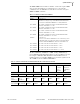
Table 4 Default Command Set—SEL-FR12 MIRRORED BITS Data Message Contents
Required SEL-651R Transmit MIRRORED BITS (SELOGIC Equations) for Default Mode
TMB1 TMB2 TMB3 TMB4 TMB5 TMB6 TMB7 TMB8
0 0 0 0 0 0 Clear link
state in
SEL-FR12
Target reset
on SEL-FR12
HMI
SEL-651R Received MIRRORED BITS (Relay Word bits)
RMB1 RMB2 RMB3 RMB4 RMB5 RMB6 RMB RMB8
Trio 1 FAULT Trio 2 FAULT Trio 3 FAULT Trio 4 FAULT Trio 1 LINK Trio 2 LINK Trio 3 LINK Trio 4 LINK