
User manual


Initial Power up and Discovering
18
SR2MAN01 11/2007
Description of
the LCD
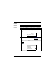
The illustration below presents an example of LCD display elements when
displaying the INPUT-OUTPUT screen:
* An ACTIVE input or output is displayed in reverse video.
Prompt Element
1 Retractable mounting feet.
2 Screw terminal block for the power supply.
3 LCD display, 4 lines, 18 characters.
4 Screw terminal block for discrete inputs.
5 Screw terminal block for analog inputs.
0-10 Volts, usable in discrete input mode depending on model.
6 Slot for backup memory or PC connection cable.
7 Shift key (white).
8 Menu/OK key (green) for selection and confirmation.
9 Relay output screw terminal block.
10 Navigation keys (gray) or after configuring Z pushbuttons.
Prompt Element
1 Input status* display (B...E represent the analog inputs, also may be used as
DISCR).
2 Display of the operating mode (RUN/STOP) and programming mode (LD/FBD).
3 Display of the date (day and time for products with clock).
4 Output status display.
5 Contextual menus / pushbuttons / icons indicating the operating modes.
2
Menu / OK
12 43
1 2 3 4 B C D E
S T O P L D
T H U 2 5 S E P 1 6 : 4 0
1 2 3 4
1
2
3
4
5