
User Manual


–13–
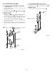
Cylinder mounting
Screw
Stator
Connector on the
CP-1 PWB assembly
Dowels
Holes
Rails
Rails
Screws
Fig.3-5-4
ASSEMBLY NOTES:
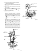
1. Align the cylinder assembly with the two dowels
on the cylinder mounting . (See Fig. 3-5-5)
2. Apply grease (VHJ-0100) to the rails of the cylinder
mounting
(grease the parts which come in contact
with the S and T incline mounting assembly). (See
Fig. 3-5-5)
3. Align the two dowels
on the cylinder mounting
with the two holes on the mechanism chassis. (See
Fig. 3-5-4)
4. After assembly, clean the tape path surface of the
cylinder (drum).
5. After replacing the cylinder mounting or the cylinder
assembly, do the tape path adjustment as instructed
in section 4-3, and do the switching position
adjustment of the servo circuit.
6) Remove the three screws
at the bottom of the
cylinder mounting
. (See Fig. 3-5-5)
3-5-2. CYLINDER MOUNTING
(See Figs. 3-5-4 and 3-5-5)
1) Put the mechanism into EJECT mode.
2) Refer to section 3-4 and remove the cleaner lever.
3) Disconnect the flexible cable connected to the
stator
.
4) Disconnect the flexible cable connected to the
connector
.
5) Remove the three screws
. Taking care not to scratch
or soil the tape path surface of the cylinder (drum), lift
the cylinder mounting
slightly, and keeping it
raised. (See Fig. 3-5-4)
Cylinder mounting
Cylinder assembly
Screws
Dowels
Fig.3-5-5