
User Manual


–11–
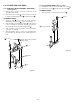
Positioning mark
Positioning mark
Main cam
Front rack gear
Fig.3-3-6
Shaft
Mounting
Plastic spring
Clamp
Cleaner lever
Clamp
Cleaner roller assembly
Plastic spring
3-3-4.START RACK GEAR AND FRONT RACK GEAR
(See Figs.3-3-5 and 3-3-6)
1) Remove the mechanism unit, referring to section 3-2.
2) Remove the cassette mechanism assembly, referring
to section 3-3-1.
3) Remove the special screw
. When you do this, slide
the front rack gear assembly
towards the front until
it stops, then take it off the shaft
. Take care not to
damage the shaft
.
4) Remove the spring
.
5) Remove the clamp
on the front rack gear , then
remove the start rack gear
.
ASSEMBLY NOTES:
1. Apply grease (VHJ-0100) to the front rack gear and
all over the inside of the groove on the start rack
gear
.
2. Align the positioning mark
on the front rack gear
with the mark on the main cam .
3. When installing the cassette mechanism assembly,
refer to section 3-3-1 and align the start rack gear with
the pinion gear.
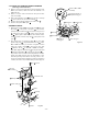
3-4. CLEANER ROLLER ASSEMBLY
(See Fig.3-4-1)
1) Remove the clamp and take out the cleaner lever
. When you do this, be careful not to bend the
plastic springs
and on the cleaner lever .
2) Remove the clamp
, and take out the cleaner roller
assembly
. Be careful not to touch the sponge on
the cleaner roller assembly
.
ASSEMBLY NOTES:
1. When mounting the cleaner lever on the shaft ,
press the clamp
in the direction shown by the
arrow, and snap it into the mounting
on the audio
R/P head assembly.
FIg.3-3-5
Fig.3-4-1
Special screw
Spring
Start rack gear
(apply grease to
inside of groove)
Front rack
gear assembly
Front rack gear
(apply grease to
inside of groove)
Shaft
Clamp