
User's Manual


page
6
/64
Note d’étude / Technical document : URD1– OTL
5665.3
– 003 / 72238 Edition 01
Document Sagemcom Reproduction et divulgation interdites
Sagemcom document. Reproduction and disclosure prohibited
FIGURES LIST
Figure 1: Block diagram of HiLoNC module ...........................................................................................................................8
Figure 2: Postage stamp sized HiLoNC V2 51 pads out front side ........................................................................................11
Figure 3: Postage stamp sized HiLoNC V2 51 pads out back side.........................................................................................11
Figure 4: SIM Card signals.....................................................................................................................................................11
Figure 5: Protections: EMC and ESD components close to the SIM .....................................................................................12
Figure 6: Protections: Serial resistors for long SIM bus lines. ...............................................................................................12
Figure 7: Audio connection ....................................................................................................................................................13
Figure 8 : Filter and ESD protection of microphone ..............................................................................................................14
Figure 9: Filter and ESD protection of 32 ohms speaker........................................................................................................14
Figure 10: Example of D class TPA2010D1 1Watt audio amplifier connections. .................................................................15
Figure 11: Buzzer connection.................................................................................................................................................16
Figure 12: Network LED connection .....................................................................................................................................17
Figure 13: GSM/GPRS Burst Current rush ............................................................................................................................17
Figure 14: GSM/GPRS Burst Current rush and VBAT drops and ripples...............................................................................18
Figure 15: Example of power supply based on a DC/DC step down converter......................................................................19
Figure 16: Example of power supply based on regulator MIC29302WU ..............................................................................19
Figure 17: Example with Linear LT1913 ...............................................................................................................................20
Figure 18: Complete V24 connection between HiLoNC V2 and host....................................................................................21
Figure 19: CTS versus POK_IN signal during the power on sequence. .................................................................................21
Figure 20: connection to a data cable .....................................................................................................................................22
Figure 21: Example of a connection to a data cable with a MAX3238E................................................................................23
Figure 22: Partial V24 connection (4 wires) between HiLoNC V2 and host .........................................................................23
Figure 23: CTS versus POK_IN signal during the power on sequence. .................................................................................24
Figure 24: Partial V24 connection (2 wires) between HiloNC V2 and host...........................................................................24
Figure 25: CTS versus POK_IN signal during the power on sequence. .................................................................................25
Figure 26: PCM interface timing ............................................................................................................................................26
Figure 27: RF_TX burst indicator ..........................................................................................................................................27
Figure 28: Backup battery or 10µF Capacitor internally charged ..........................................................................................28
Figure 29: Charging curve of backup battery .........................................................................................................................28
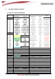
Figure 30 : HiLoNC V2 51 pads with their power domains...................................................................................................30
Figure 31 : HiLoNC V2 51 pads with their power domains…continued ...............................................................................31
Figure 32: Digital Pad-out clamp diode..................................................................................................................................32
Figure 33: Hardware interface diodes solution between HiLoNC V2 and host......................................................................33
Figure 34: Hardware interface buffers solution between HiLoNC V2 and host.....................................................................33
Figure 35: Power ON sequence ..............................................................................................................................................35
Figure 36: Full UART signals during the power on sequence................................................................................................36
Figure 37: Diagram for the power on .....................................................................................................................................37
Figure 38: Diagram for the sleep mode ..................................................................................................................................38
Figure 39: Reset command of the HiLoNC V2 by an external GPIO ....................................................................................39
Figure 40: Power supply command by a GPIO ......................................................................................................................40
Figure 41: Power OFF sequence for POK_IN, VGPIO and CTS...........................................................................................40
Figure 42: Power consumption at DRX9 (with RS-NGMO2 power supply) .........................................................................41
Figure 43: Antenna connection...............................................................................................................................................43
Figure 44: Antenna detection circuit ......................................................................................................................................44
Figure 45: Mandatory area for varnish ...................................................................................................................................45
Figure 46: Connection of RF lines with different width.........................................................................................................45
Figure 47: Layout of audio differential signals on a layer n...................................................................................................48
Figure 48: Adjacent layers of audio differential signals .........................................................................................................48
Figure 49: layer allocation for a 6 layers circuit.....................................................................................................................49
Figure 50: Factory Tape dimensions ......................................................................................................................................50
Figure 51 : Solder mask design ..............................................................................................................................................51
Figure 52 : Typical thermal profile.........................................................................................................................................52
Figure 53 : Flexjet nozzle 340F..............................................................................................................................................53
Figure 54 : Siemens nozzle 417..............................................................................................................................................53
Figure 55 : Fiducials positions................................................................................................................................................54
Figure 56 : Underfill injection holes.......................................................................................................................................55
Figure 57 : Laboratory hot plate to unsolder the module........................................................................................................56