
Product Manual


INSTALLATION
LOCATION:
• Locate the compressor in a cool, dry, clean and well-ventilated area with a temperature range between 35° and
105°F. WARNING! Under no circumstances should the air compressor be installed in an area that may be
exposed to a dirty, corrosive atmosphere, toxic vapors or volatile fumes. Do not store toxic, volatile or corrosive
agents near the compressor.
• The intake filter may be remotely located. Enlarge size of intake piping by 1/4” in size for each 10 feet of length.
• Install so that the flywheel/belt guard is at least 18” from an adjacent wall. Allow space on all sides for air
circulation and ease of maintenance.
• Make sure the compressor tank is mounted level on a solid foundation using vibration dampening pads made of
felt/rubber. If vibration pads cannot be located, the skid on which the compressor is shipped may be left on and
used as a mounting base. Solid shims may be used to level unit before bolting or lagging unit to prevent
movement.
NOTE: Contact your local ROLAIR representative for information on level-rite mounting pads or if excessive vibration
or movement is noticed upon initial test run. When hard-mounting a gas-powered air compressor on a trailer or a
truck bed, leave one of the four mounting bolts looser than the others (slightly beyond hand-tight) to help minimize
vibration and improve the overall performance and life of the unit.
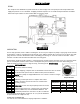
ELECTRICAL CONNECTIONS AND MOTOR WIRING:
Most stationary ROLAIR compressors are shipped without a power cord. All power cords attached to this machine
must be properly grounded and installed by a qualified electrician with knowledge of the National Electrical Code
(N.E.C.), OSHA Code and/or any local/state/provincial codes having precedence. Failure to abide by applicable
electrical codes may result in personal injury or property damage.
Check the electrical supply for voltage, phase and frequency to see that they match the nameplate stampings on the
motor, magnetic starter, solenoids and other controls. Use electrical wires of adequate size to carry the full load
current of the motor without excessive voltage drop.
NOTE: Do not use a generator as the power source. Air compressors use inductive motors that require 3-5 times
the full-load amp draw to properly start. Most generators will not provide the wattage needed to properly start
this type of electric motor.
The motor must always be protected by a starter with properly sized thermal overload(s). The starter should protect
the motor from overheating and burn-out due to an overload, low voltage or single phasing of a 3-phase circuit. Failure
to install the proper starter and overloads will void the motor manufacturer’s warranty. Follow the National Electric
Code or local electric code in providing wiring, fusing and disconnect switches.
After the wiring is completed, momentarily start the motor to make certain that the compressor flywheel rotates in the
same direction as indicated by the direction arrow on the compressor flywheel.
NOTE: An easy way to check for proper rotation is to place a piece of paper on the outside of the belt guard
cover while the machine is running. If the piece of paper is blown away, the rotation is incorrect. Consult a
qualified electrician to correct the rotation. Improper rotation will lead to overheating and oil blowing out of the
crankcase breather.
PIPING FIT-UP:
Always position air compressor to avoid an excessive amount of tension between the external air lines and connection
at the air tank. The piping should be lined up without having to spring or twist it into position. Adequate expansion
loops or bends should be installed to prevent undue stresses at the compressor resulting from the changes between
hot and cold conditions. Pipe supports should be mounted independently of the compressor and anchored as
necessary to limit vibration and prevent expansion strains.
*Never join pipes or fittings with lead-tin soldering. Welded or threaded steel pipes and cast-iron fittings, designed for
the pressures and temperatures, are recommended. Never use PVC or plastic pipe.
Pipe sizes for compressed air lines
Air
CFM
Length of Pipe Lines in Feet
25 50 75 100 150 200 250 300
1-5 1/2 1/2 1/2 1/2 1/2 1/2 1/2 1/2
10 1/2 1/2 1/2 3/4 3/4 3/4 3/4 3/4
15 1/2 3/4 3/4 3/4 3/4 3/4 3/4 3/4
25 3/4 3/4 3/4 3/4 3/4 1 1 1
30 3/4 3/4 3/4 3/4 1 1 1 1
35 3/4 3/4 1 1 1 1 1 1
40 3/4 1 1 1 1 1 1 1
60-70 1 1 1 1 1-1/4 1-1/4 1-1/4 1-1/4
80-100 1-1/4 1-1/4 1-1/4 1-1/4 1-1/2 1-1/2 1-1/2 1-1/2
Check all piping and fittings regularly to avoid leaks in the system.