
User Manual


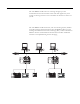


Table Of Contents
- 1756-UM532A-EN-P
- Important User Information
- Table of Contents
- Purpose of This Manual
- Preface
- 1756-DH485 Module Overview
- Overview of the DH-485 Network
- Introduction
- DH-485 Network Description
- DH-485 Network Protocol
- DH-485 Token Rotation
- DH-485 Network Initialization
- Devices that Use the DH-485 Network
- 1747-AIC Isolated Link Coupler for DH-485
- 1761-NET-AIC Advanced Interface Converter Product Overview
- Operating Modes
- Device Compatibility
- Misconception about the 1761-NET-AIC Converter
- 1747-UIC USB to DH-485 Interface Converter
- Example System Configuration
- Important Planning Considerations
- Additional Resources
- Use Data Highway 485 Network
- Use RSLinx Software to Create a Routing Table
- Communicate from an SLC 5/03 Controller to a Logix Controller over a DH-485 Network
- Communicate Between SLC Controllers over DH+ and DH485 Networks
- Communicate Between a PLC-5 Controller and a Remote SLC 5/03 Controller over Multiple DH-485 Networks
- Communicate from an SLC 5/05 Controller to an SLC 5/03 Controller over an EtherNet/IP Network
- Communicate to a SLC 5/03 Controller on a DH-485 Network
- Communicate from a Logix Controller to an SLC 5/03 Controller over EtherNet/IP and DH-485 Networks
- Specifications
- Troubleshoot the 1756-DH485 Module
- Index
- How Are We Doing?
- Rockwell Automation Support
- Backcover
Publication 1756-UM532A-EN-P - May 2006
1756-DH485 Module Overview 1-9
Alphanumeric Indicators
When you apply power to the module, the alphanumeric display begins to
cycle through the following sequence.
1. All LEDs flash on then off -CHA, CHB OK
2. OK displays red then changes to green.
3. INIT displays.
4. Firmware Revision flashes on scrolling display: DH-485
5. Channel A and the network used for channel A.
6. Channel A node address.
7. Channel A status.
8. Channel B and the network used for channel.
9. Channel B node address.
10. Channel B status.
This sequence runs continuously during normal module operation.
Refer to Appendix B, Troubleshoot the 1756-DH485 Module and publication
1756-IN587, the ControlLogix DH-485 Communications Module Installation
Instructions, for more information about LEDs and status indicators.
EXAMPLE
For example, if your module uses the following:
• Channel A for DH-485 with node address 14
• Channel B is not connected
and the channels are operating properly, you see the
following sequence:
A DH, A#14, A OK, B DH, B#00, ONLY NODE