
User's Manual


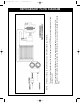


INSTALLATION OF OPTIONAL 80% TANK
CAPACITY SENSING COMPONENTS (KIT: KT-5001)
18
Note: ROBINAIR also offers the model, 25176B-KT,
with the 80% Capacity Shut Off Kit installed at the
factory.
c Warning: Prior to performing any type of mainte-
nance work on your 25176B, insure that it is discon-
nected from the power supply before you begin.
NOTE: Refer to the wiring diagram at the bottom of
page 17 during installation of your kit.
1. Disconnect your 25176B from the power source
2. Remove the fasteners from each side of the
25176B and separate both halves of the plastic
case.
Note: You may find it more convenient to disconnect
the two wires to the fan, if so remember to reconnect
them prior to re-installing the case.
3. Place the metal frame of the 25176B in the
upright position
4. Remove the "pry out plug" from the hole located
at the lower right of the front panel, and pass the
tank sensor cord (p/n EL1420) through it.
5. Visually identify the two studs located on the
left side of the front panel. (this will be the location
for the relay, p/n EL1500, after
all your electrical
connections are made.)
6. Locate the three red wires connected to the pres-
sure switch (directly below the start switch) and
disconnect the wire coming from the power
switch.
7. Ensure that the terminal multiplier (p/n EL1221) is
placed on terminal #4 of the relay and then place
the red wire removed from the high pressure
switch on that terminal.
8. Place the black wire from the sensor cord on the
other side of the terminal multiplier, on the same
terminal #4 of the relay.
9. Place the white wire from the sensor cord on
terminal #0 of the relay.
10. Connect the white wire from the male side of the
3 pin connector (p/n EL1215) to terminal #1 of
the relay.
Note: Ensure that the green wire from the sensor
cord is connected to the center of the 3-pin connec-
tor. (Note: only two wires are used in this connector).
11. Connect the 3-pin connector to its female coun-
terpart, already pre wired on your 25176B.
Note: make sure the two wires, (1) green and (1)
white, are in the proper position (directly across)
from their mating wires.
12. Connect one end of the red wire (p/n WR1403),
supplied with your kit, to terminal #2 of the relay
and the other end to the high pressure switch.
13. Secure the relay onto the two studs mentioned in
Step 5, using the hardware already installed on
the studs.
14. Secure the tank sensor into the hole in the front
panel with the strain relief grommet provided.
15. Replace the fan wires, if removed in step # 2.
16. Secure any loose wiring with the wire ties pro-
vided.
17. Replace the plastic case halves and fasteners.
18. Test the installation by momentarily attempting
to start the 25176B without the sensor cord con-
nected to a tank sensor. The unit’s compressor
should not start up. Turn the 25176B off and
re-attempt to start the unit with the sensor cord
connected to a tank with a tank capacity sensor.
The unit should function normally. Disconnecting
the sensor cord while the unit is running should
cause the unit to shut down.
19. If your unit does not function per above, DIS-
CONNECT the 25176B from the Power Supply,
and re-check your connections per the above
steps and the wiring diagram at the bottom of
page 17.
ROBINAIR offers the model, 25176B-KT, with the 80% Capacity Shut Off Kit (p/n KT-5001) installed
at the factory. On this model, when used with a recovery tank that has an internal float switch, the
recovery unit will automatically shut off when the recovery tank is 80% full.
25176B-KT MODEL
100439_RevC.qxd 9/2/05 3:02 PM Page 17